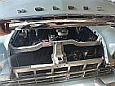
It's an old coopers brewing kit converted into a cheap cyclone dust converter. Mainly for the drop saw and the sandblasting cabinet.Blacky wrote: Fri Oct 24, 2025 10:27 am Very thorough and top quality work as always, I gotta ask , whats with the dust collector looking bizzo mounted on the office chair base ???
Ol' Rusty - FB/EK Sedan
-
funkyscooter

- Posts: 705
- Joined: Wed Aug 16, 2017 8:12 am
- State: NSW
- Location: Sydney
Re: Ol' Rusty - FB/EK Sedan
Scott
(Not so rusty) Ol' Rusty - FB/EK Sedan
(Not so rusty) Ol' Rusty - FB/EK Sedan
-
funkyscooter
- Posts: 705
- Joined: Wed Aug 16, 2017 8:12 am
- State: NSW
- Location: Sydney
Re: Ol' Rusty - FB/EK Sedan
Boot Popper!
A couple years back I thought it would be a good idea to shave the boot lock and install an electronic solenoid.
I bodged something up at the time that used a lever located in the lock cam thingy shaft that twists when you turn the key, but was never happy. There’s also the issue of accessing a flat battery in the boot that you can only open electronically. As shaving the lock his not a deal breaker, I kinda left it in the too hard basket and moved on.
Well, after having a win with the bonnet lock/door lock solenoid, I dusted off the this thing for another crack.
To the drawing board. First draw a to scale cross section of the boot and lock mechanism.
Then work out a lever that will pull the arm on the lock the required distance( ~ 15mm), given that the solenoid has a maximum pull of 22mm.
Connect lever to solenoid with piece of bike spoke bent in a jaunty fashion (took many attempts to get it to move freely).
Lock lever on pivot bolt with minimal play but no binding (2 bolts locked together in a threaded hex joiner).
Cut solenoid bracket down to fit, redrill and weld on nuts and hex joiner.
Some time later after many test fits I have this.
Not much to look at so if I peek down from the top with my phone you can get a better idea.
There was a surprising amount of unused room in here - perfect for a comically oversized solenoid. Installing is a fiddle, you drop the solenoid from the top, feed the base with lever and cable attached to the dangling lock through the lock hole in the bottom of the boot, screw the solenoid to the base after attaching the bike spoke, then bolt the base down with 3 screws and fit the boot lock.
Here it is on the bench to give you a better idea.
Flat battery issue will be partly solved by having a positive post in the engine bay, and partly solved by adding an after market bonnet release attached directly to the lock which will most likely live loose under the rear seat for emergency access.
A couple years back I thought it would be a good idea to shave the boot lock and install an electronic solenoid.
- Screenshot 2025-11-02 at 6.17.00 PM.jpg (304.23 KiB) Viewed 5067 times
Well, after having a win with the bonnet lock/door lock solenoid, I dusted off the this thing for another crack.
To the drawing board. First draw a to scale cross section of the boot and lock mechanism.
- IMG_8171.jpeg (925.15 KiB) Viewed 5067 times
Connect lever to solenoid with piece of bike spoke bent in a jaunty fashion (took many attempts to get it to move freely).
Lock lever on pivot bolt with minimal play but no binding (2 bolts locked together in a threaded hex joiner).
Cut solenoid bracket down to fit, redrill and weld on nuts and hex joiner.
Some time later after many test fits I have this.
- IMG_8163.jpeg (733.18 KiB) Viewed 5067 times
- IMG_8162.jpeg (648.33 KiB) Viewed 5066 times
Here it is on the bench to give you a better idea.
- IMG_8167.jpeg (722.67 KiB) Viewed 5067 times
- IMG_8172.jpeg (911.67 KiB) Viewed 5067 times
- IMG_8169.jpeg (737.46 KiB) Viewed 5067 times
- IMG_8207.jpg (808.99 KiB) Viewed 5067 times
Scott
(Not so rusty) Ol' Rusty - FB/EK Sedan
(Not so rusty) Ol' Rusty - FB/EK Sedan
Re: Ol' Rusty - FB/EK Sedan
Good stuff - I will need to go through this process for the 2 door 

I started with nothing and still have most of it left.
Foundation member #61 of FB/EK Holden club of W.A.
Foundation member #61 of FB/EK Holden club of W.A.
Re: Ol' Rusty - FB/EK Sedan
This looks good. Just got to find time to read properly.
Sent from my iPhone using Tapatalk
Sent from my iPhone using Tapatalk
getting my FB ute on the road
EK van on rotisserie
EK van on rotisserie
Re: Ol' Rusty - FB/EK Sedan
It wasn’t that long after all. Neat as a pin Scotty.
FB ute fixer upper, EK van on rotisserie
FB ute fixer upper, EK van on rotisserie
getting my FB ute on the road
EK van on rotisserie
EK van on rotisserie
-
funkyscooter
- Posts: 705
- Joined: Wed Aug 16, 2017 8:12 am
- State: NSW
- Location: Sydney
Re: Ol' Rusty - FB/EK Sedan
SU Carb Overhaul
So over the last few months I have gone from this
To this
Been a bit of a journey. This is the way I did it - not suggesting it is the way to do it, but it worked for me.
First up, strip down carbs, check shaft for slop, of which there was a fair bit, so ordered a twin and single overhaul kit from SU Midel, which took a phone call to explain my weird left and right fuel bowl set up that I inherited.
Sandblasted everything using a fine grit that is almost like talcum powder and is meant to be used to etch glass. Can’t see a thing when blasting through the cloudy mist but seemed to work. Taped up all orifices to keep most of the grit out the inside.
Here is a before after.
And a complete set
Pays to read more and watch less YouTube, as at this point I assumed both the shafts and bushings where worn and needed to be replaced As I am impatient, while I was waiting to receive the overhaul kits, I went ahead and started to drill out the old bushings. We will never know if the new shafts would have been fine in the old bushing.
Built a jig with the 3D printer to hold the carb body square to the drill press (which is reasonably rigid for a cheapie). Used a 5/16 guide punch through both bushings to hold it in place whilst tightening everything up.
Again, at this point logic says that if the guide pin is sitting snugly in the bushing and they are good enough to square it all up, then maybe the bushings are not worn and don’t need to be replaced. No time for logic - I’ve got some drilling to do. Replacement bushings are 3/8 (9.5mm) so went with 3/8 drill. This is a spare carb body I had to test with.
Key here is to not drill through to the centre of the carb as it will make it out of round and air can then leak around the throttle disk. This drill press has a depth display so used that to make sure I didn’t go through.
So over the last few months I have gone from this
- IMG_7927.jpeg (947.73 KiB) Viewed 4999 times
- IMG_8276.jpeg (921.11 KiB) Viewed 4999 times
- IMG_8274.jpeg (1.06 MiB) Viewed 4999 times
First up, strip down carbs, check shaft for slop, of which there was a fair bit, so ordered a twin and single overhaul kit from SU Midel, which took a phone call to explain my weird left and right fuel bowl set up that I inherited.
Sandblasted everything using a fine grit that is almost like talcum powder and is meant to be used to etch glass. Can’t see a thing when blasting through the cloudy mist but seemed to work. Taped up all orifices to keep most of the grit out the inside.
Here is a before after.
- IMG_7938.jpeg (962.6 KiB) Viewed 4999 times
- IMG_7939.jpeg (653.13 KiB) Viewed 4999 times
Built a jig with the 3D printer to hold the carb body square to the drill press (which is reasonably rigid for a cheapie). Used a 5/16 guide punch through both bushings to hold it in place whilst tightening everything up.
- IMG_7961.jpeg (937.97 KiB) Viewed 4999 times
- IMG_7971.jpeg (908.98 KiB) Viewed 4999 times
- IMG_7982.jpg (981.83 KiB) Viewed 4999 times
Scott
(Not so rusty) Ol' Rusty - FB/EK Sedan
(Not so rusty) Ol' Rusty - FB/EK Sedan
-
funkyscooter
- Posts: 705
- Joined: Wed Aug 16, 2017 8:12 am
- State: NSW
- Location: Sydney
Re: Ol' Rusty - FB/EK Sedan
Could have gone ahead and drilled the three bodies out, but got paranoid that the OD of the replacement bushings might be different to the listed size, so while I waited for the referb kit, I went ahead and dealt with another problem. Crank case breather, which is plumbed directly to the manifold, leaving the 3 pipes on the carbs attractively plugged up thus…
Time to delete, with the option of adding back in the future with the addition of a threaded plug. Cut the pipes off, made a new jig, this time at a jaunty 50 degrees, and applied the same logic to drilling out the bushings.
No going back now.
Tap in the drill and hand cranked it to thread the body.
Done
Referb kits arrived, confirmed new split bushings are 9.5mm, and got to drilling. Went with a high speed, drilled down very slowly, with loads of cutting fluid.
Made sure I stopped in time before drilling through.
Took a while with 6 sides but got there.
- IMG_7919.jpeg (735.31 KiB) Viewed 4999 times
- IMG_8017.jpeg (910.24 KiB) Viewed 4999 times
- IMG_8018.jpeg (850.14 KiB) Viewed 4999 times
- IMG_8019.jpeg (986.71 KiB) Viewed 4999 times
- IMG_8022.jpeg (1.12 MiB) Viewed 4999 times
- IMG_8035.jpeg (772.39 KiB) Viewed 4999 times
- IMG_8036.jpeg (885.36 KiB) Viewed 4999 times
- IMG_8038.jpeg (1.04 MiB) Viewed 4999 times
Scott
(Not so rusty) Ol' Rusty - FB/EK Sedan
(Not so rusty) Ol' Rusty - FB/EK Sedan
-
funkyscooter
- Posts: 705
- Joined: Wed Aug 16, 2017 8:12 am
- State: NSW
- Location: Sydney
Re: Ol' Rusty - FB/EK Sedan
Used the jig again to help square things up while I used a centre punch in the drill to press the bushings in.
IMG_8042
And done.
Now dealing with the most important part - reaming the new bushings out to 5/16. From my newfound knowledge from You Tube, what I needed was a 5/16 reamer with a long pilot to guide the reamer through both bushing. Looked around for a bit and found a company that made what I thought was going to be a long piloted 5/16 reamer. After a 4 week wait, this arrived.
.
Ahh - okay a little shorter than I anticpated. Unfortunately no turning back now as the new bushings need to get reamed, and not knowing a trusted machinist, I decided to stick with the plan and ream it myself. Spent a bit of time fine tuning my jig and how it mounts in the drill. Lasers were even involved.
Did not get one photo of reaming these out, as things were a little tense at this point and no time for action shots. But here is a pic of the first test fit of the new shaft. No binding and no slop, and visually looks like a tight fit. Time will tell.
Maybe not the smartest way to do this, but with a custom reamer with a long pilot I would have been a lot more confident of success. In the end, it just required a bit of patience and time when mounting each body for reaming.
- IMG_8042.jpeg (698.38 KiB) Viewed 4999 times
And done.
- IMG_8043.jpeg (650.55 KiB) Viewed 4999 times
- IMG_8227.jpeg (978.16 KiB) Viewed 4999 times
Ahh - okay a little shorter than I anticpated. Unfortunately no turning back now as the new bushings need to get reamed, and not knowing a trusted machinist, I decided to stick with the plan and ream it myself. Spent a bit of time fine tuning my jig and how it mounts in the drill. Lasers were even involved.
- IMG_8225.jpeg (833.67 KiB) Viewed 4999 times
- IMG_8226.jpeg (790.98 KiB) Viewed 4999 times
Scott
(Not so rusty) Ol' Rusty - FB/EK Sedan
(Not so rusty) Ol' Rusty - FB/EK Sedan
-
funkyscooter
- Posts: 705
- Joined: Wed Aug 16, 2017 8:12 am
- State: NSW
- Location: Sydney
Re: Ol' Rusty - FB/EK Sedan
Next up - stainless heat shield. Don’t really like how close the front carb float bowl is to the exhaust.
So did a bit of CAD
Being a tight arse I tried to use a bit of 0.5mm stainless exhaust fan shroud.
Ok call that a test, remade the wooded buck and spent $45 on a piece of 600x300 0.9mm 316 sheet. Started forming.
Cut holes for the linkages and the intakes, and discovered an issue with the linkages fowling on the shield. Missed it by that much.
Two ways I could have gone, cut it or form it. I went with the latter for neatness.
With forming success I decided to do a bit more and add a bit of strength with a couple of vertical ribs. Welded up the corners, grind it and 120 grit on the DA for the win.
Hopefully this will prevent embarrassment at the petrol station when trying to restart a hot engine in the future.
- IMG_7997.jpeg (939.75 KiB) Viewed 4999 times
- IMG_8032.jpeg (1.02 MiB) Viewed 4999 times
- IMG_8061.jpeg (979.1 KiB) Viewed 4999 times
- IMG_8130.jpeg (810 KiB) Viewed 4999 times
- IMG_8229.jpeg (632.8 KiB) Viewed 4999 times
- IMG_8234.jpeg (978.18 KiB) Viewed 4999 times
- IMG_8246.jpeg (984.84 KiB) Viewed 4999 times
- IMG_8250.jpeg (952.46 KiB) Viewed 4999 times
Scott
(Not so rusty) Ol' Rusty - FB/EK Sedan
(Not so rusty) Ol' Rusty - FB/EK Sedan

Re: Ol' Rusty - FB/EK Sedan
Very neat work 
Cheers,
Harv
Cheers,
Harv
327 Chev EK wagon, original EK ute for Number 1 Daughter, an FB sedan meth monster project and a BB/MD grey motored FED.
Re: Ol' Rusty - FB/EK Sedan
You have way more patience than I have mate 
I started with nothing and still have most of it left.
Foundation member #61 of FB/EK Holden club of W.A.
Foundation member #61 of FB/EK Holden club of W.A.
-
In the Shed
- Posts: 2240
- Joined: Wed May 16, 2012 10:18 pm
- State: SA
- Location: South Australia
Re: Ol' Rusty - FB/EK Sedan
Looks great Scott. Tight arse?? I call it recycling and being savvy! You did well forming s/steel which can be a pain to work & drill compared to plain steel sheet. Was the 0.5mm too thin to hold its shape??
A day in the shed beats a day at work!
-
funkyscooter
- Posts: 705
- Joined: Wed Aug 16, 2017 8:12 am
- State: NSW
- Location: Sydney
Re: Ol' Rusty - FB/EK Sedan
Yeah the 0.5 ended up being a wavy mess and was still not very rigid even with bends and a couple beads for strength. And your right, stainless takes a lot of work to get it to form - think I spent about 3 hours hammer forming those two beads. At least it is nice and thick for welding so no issues with blow through.In the Shed wrote: Thu Nov 20, 2025 10:58 pm You did well forming s/steel which can be a pain to work & drill compared to plain steel sheet. Was the 0.5mm too thin to hold its shape??
Scott
(Not so rusty) Ol' Rusty - FB/EK Sedan
(Not so rusty) Ol' Rusty - FB/EK Sedan
-
funkyscooter
- Posts: 705
- Joined: Wed Aug 16, 2017 8:12 am
- State: NSW
- Location: Sydney
Re: Ol' Rusty - FB/EK Sedan
Also probably should have mentioned re drilling out the bushing - I re-profiled the drill bit to reduce the angle till it was almost flat so it wouldn't bite too much into the soft brass. That made a huge difference when controlling the drill press.
Scott
(Not so rusty) Ol' Rusty - FB/EK Sedan
(Not so rusty) Ol' Rusty - FB/EK Sedan
Re: Ol' Rusty - FB/EK Sedan
Neat job Scotty. I’ve got a sheet of 1mm aluminium I plan on using, but project currently shelved.
Sent from my iPhone using Tapatalk
Sent from my iPhone using Tapatalk
getting my FB ute on the road
EK van on rotisserie
EK van on rotisserie