Good one Harv,
Relating to NCOP with the tyre size is this for tyres without certification ?
Also I would love to see the back where the brackets bolt to behind the disc.
Great job mate looking forward to the final result.
Greg
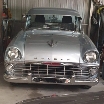
Harv's meth monster project
Re: Harv's meth monster project
So many cars so little time!

Re: Harv's meth monster project
The 205 tire limit is for uncertified cars. NCOP SECTION LS Tyres, Rims, Suspension and Steering allows
a) 15mm larger diameter (or 26mm smaller),
b) requires the aspect ratio to be within 10 between front/rear (eg a 205/65/13 rear and a 205/55/13 front),
c) requires the difference in front/rear width to be no more than 30%,
d) will not allow you to run a narrower tire than factory (no front runners), and
e) a width increase of no more than 30%.
Table LS2 spells this out a bit better. For an FB/EK with original 6.4" tires (165) the table allows a maximum of 205's. It allows that if you are running a 65-85 aspect ratio then a 7.5" rim is OK, and if you reduce the aspect ratio to 60 or below then 8" is OK.
Interestingly, NCOP then goes silent for tire width, unless you are doing a (4WD) body lift modification. I guess in theory there are then no limits on what the engineer can approve, provided you meet the track limits (no more than 25mm track increase, certified or un-certified).
I'll take some photos of the bracket setup over the weekend.
Cheers,
Harv
327 Chev EK wagon, original EK ute for Number 1 Daughter, an FB sedan meth monster project and a BB/MD grey motored FED.
Re: Harv's meth monster project
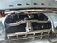
Rough photo of how the caliper brackets attach:
Forgive the four bolts (three in the photo) that hold the bracket to the stub axle - they should not be there. You drill and tap the four stub axle holes to 7/16UNF, then bolt through from the inside. No protruding nuts/bolt heads on the spindle side. I've just used undersized bolts to hold it together for now.
The spacer is needed because the bracket goes between the steering arm and stub axle on only one end. The spacer squares up the steering arm. I've got the bracket on the rear bolt of the steering arm (which puts the calipers to the front of the disc). In theory, you can flip the bracket, put the spacer on the front bolt of the steering arm, and mount the calipers to the rear too.
More checking/looking shows that bracket/spacer makes the steering arm come inboard. On a hard turn, the steering arm now hits the lower control arm before the kingpin stops lock up. See the blue circle below.
Dumb question (best to sense check here before I ask the engineer and confirm my stupidity): would it be OK to grind a small amount off the edge of the lower control arm? Not sure how much, but might be 5mm. Gut feel is that the control arm is too rigid to bend out of the way with a BFH. I'm normally adverse to grinding suspension or steering components, though note that the CRS bracket kit suggests grinding of the stub axle (for other reasons). Feels smarter to grind the control arm rather than the steering arm.
Views?
Cheers,
Harv
- temporary fit-up.jpg (631.18 KiB) Viewed 1181 times
Forgive the four bolts (three in the photo) that hold the bracket to the stub axle - they should not be there. You drill and tap the four stub axle holes to 7/16UNF, then bolt through from the inside. No protruding nuts/bolt heads on the spindle side. I've just used undersized bolts to hold it together for now.
The spacer is needed because the bracket goes between the steering arm and stub axle on only one end. The spacer squares up the steering arm. I've got the bracket on the rear bolt of the steering arm (which puts the calipers to the front of the disc). In theory, you can flip the bracket, put the spacer on the front bolt of the steering arm, and mount the calipers to the rear too.
More checking/looking shows that bracket/spacer makes the steering arm come inboard. On a hard turn, the steering arm now hits the lower control arm before the kingpin stops lock up. See the blue circle below.
- ready for disks.png (4.28 MiB) Viewed 1181 times
Dumb question (best to sense check here before I ask the engineer and confirm my stupidity): would it be OK to grind a small amount off the edge of the lower control arm? Not sure how much, but might be 5mm. Gut feel is that the control arm is too rigid to bend out of the way with a BFH. I'm normally adverse to grinding suspension or steering components, though note that the CRS bracket kit suggests grinding of the stub axle (for other reasons). Feels smarter to grind the control arm rather than the steering arm.
Views?
Cheers,
Harv
327 Chev EK wagon, original EK ute for Number 1 Daughter, an FB sedan meth monster project and a BB/MD grey motored FED.
Re: Harv's meth monster project
I'd be inclined to machine away one spacer thickness from the front pad of the steering arm, and delete the spacer at the rear bolt hole of the steering arm. Removal of material from the front pad of the steering arm should not affect the steering arm's strength, because there's a big bolt holding it to the steering knuckle. Doing it this way will also restore the correct toe-out on turns.
Are the mounting holes in the caliper adapter 7/16", which is why you're instructed to rework the holes in the stub axle to 7/16" UNF? I'm wondering whether you couldn't make up some shoulder-shaft bolts, with 7/16" shaft and 3/8" UNF threads.
Rob
Are the mounting holes in the caliper adapter 7/16", which is why you're instructed to rework the holes in the stub axle to 7/16" UNF? I'm wondering whether you couldn't make up some shoulder-shaft bolts, with 7/16" shaft and 3/8" UNF threads.
Rob
Re: Harv's meth monster project
I like the thinking on machining the steering arms - thankyou.
The caliper holes are not threaded. Bolt goes in from behind, through the bracket (sloppy) then tightens into the (freshly tapped) stub axle holes. Done that way to make no bolt heads protrude on the spindle side... it is very busy in that area with rotor-to-hub bolts protuding near the oil seal. T
The four backing plate holes on each spindle are 3/8” diameter (to allow the factory 9/16”AF bolts to pass through). Easy to drill the four bolt holes out on each side of the car (total of eight holes) with a 25/64” drill bit, then tap the eight holes with a 7/16-20UNF tap.
Cheers,
Harv
327 Chev EK wagon, original EK ute for Number 1 Daughter, an FB sedan meth monster project and a BB/MD grey motored FED.
Re: Harv's meth monster project
If you are referring to the bit of control arm that protrudes past the pivot pin nut harv, I have massaged these in the past with said BFH to good effect. This was the top arm, to obtain clearance to some mags. Possibly bottom arm is different of course.
If those backing plate retaining holes are 3/8" then bolts must be 5/16" surely, not 9/16". Sorry to be pedantic.
Sent from my SM-G973F using Tapatalk
If those backing plate retaining holes are 3/8" then bolts must be 5/16" surely, not 9/16". Sorry to be pedantic.
Sent from my SM-G973F using Tapatalk
getting my FB ute on the road
EK van on rotisserie
EK van on rotisserie
Re: Harv's meth monster project
Harv,
You could reshape the arms and problem solved.
I have done this before but you need an oxy to get the arms red/orange hot and a press to bend them. You must also let them cool as slow as possible, I did this in a bucket full of sand, covering them and leave them overnight.
Greg
You could reshape the arms and problem solved.
I have done this before but you need an oxy to get the arms red/orange hot and a press to bend them. You must also let them cool as slow as possible, I did this in a bucket full of sand, covering them and leave them overnight.
Greg
So many cars so little time!
Re: Harv's meth monster project
Aha. This is good knowledge. I'd rather smack the control arm out of the way (and keep the meat) than grind the control arm back. If the engineer is not OK with machining the steering arms (Plan A), then this will be Plan B.Errol62 wrote: Fri Jan 29, 2021 9:51 pm If you are referring to the bit of control arm that protrudes past the pivot pin nut harv, I have massaged these in the past with said BFH to good effect. This was the top arm, to obtain clearance to some mags. Possibly bottom arm is different of course.
Pedantic is good right nowErrol62 wrote: Fri Jan 29, 2021 9:51 pmIf those backing plate retaining holes are 3/8" then bolts must be 5/16" surely, not 9/16". Sorry to be pedantic.
Sounds like a good Plan C if I can't get the control arm to bend with Clay's BFH. Harder though, as I need to pull the control arms out and guesstimate how much bend. It would be just my luck to bend the control arm, and deform the pivot pin hole at the same time. The BFH process has the pin in place, so unlikely to bugger it too much.EK283 wrote: Fri Jan 29, 2021 11:05 pmYou could reshape the arms and problem solved.
I have done this before but you need an oxy to get the arms red/orange hot and a press to bend them. You must also let them cool as slow as possible, I did this in a bucket full of sand, covering them and leave them overnight.
Some rough measuring (this is a casting, not a machined item) shows that the steering arm would probably need cutting back like this:
- Steering arm machining to embed caliper bracket.png (4.63 MiB) Viewed 1145 times
Apologies for reverting to metric measurements... its likely the way the engineer will think. Time for a conversation with him.
Cheers,
Harv
327 Chev EK wagon, original EK ute for Number 1 Daughter, an FB sedan meth monster project and a BB/MD grey motored FED.
Re: Harv's meth monster project
Even if you distort the hole a couple of tacks with the mig should help tighten things up I would think. Oh I forgot, welding not your strong point.
FB ute fixer upper, EK van on rotisserie
FB ute fixer upper, EK van on rotisserie
getting my FB ute on the road
EK van on rotisserie
EK van on rotisserie
Re: Harv's meth monster project
Your right Harv, it would be difficult to bend in that location.
How thick can you have the spacer ?
You could mill the pad on the bracket side just enough to gain the clearance but still use a spacer so as to remove as little as possible from the arm.
You could then trim the control arm a mm or two as well to gain the required spacing.
Greg
How thick can you have the spacer ?
You could mill the pad on the bracket side just enough to gain the clearance but still use a spacer so as to remove as little as possible from the arm.
You could then trim the control arm a mm or two as well to gain the required spacing.
Greg
So many cars so little time!
Re: Harv's meth monster project
Oh by the way,
I would suggest the steering arms are forged not cast so there is some strength there.
Greg
I would suggest the steering arms are forged not cast so there is some strength there.
Greg
So many cars so little time!

Re: Harv's meth monster project
Harv I had to bend my HR steering arms for Frank because of the offset of the commodore rims on the front and used the oxy torch method that Greg described and it worked well I think a lot easier to control the amount your bending them than with the BFH method 

Member of WA FB/EK Car Club
Frankenstein EK V6 Ute
The Reverend FB Station Wagon Project
Frankenstein EK V6 Ute
The Reverend FB Station Wagon Project
Re: Harv's meth monster project
The boily brother-in-law has banned me from buying a MIG… reckons if I can’t stick weld then there is little hope for me.Errol62 wrote: Sat Jan 30, 2021 9:20 amEven if you distort the hole a couple of tacks with the mig should help tighten things up I would think. Oh I forgot, welding not your strong point.
Not a bad idea. The spacer can be 0 - 8mm. Sounds like a little of Plan A, and a little of Plan B (call it Plan D). Might be the go if the engineer doesn’t like Plan A or Plan B.EK283 wrote: Sat Jan 30, 2021 9:22 amHow thick can you have the spacer ?
You could mill the pad on the bracket side just enough to gain the clearance but still use a spacer so as to remove as little as possible from the arm.
You could then trim the control arm a mm or two as well to gain the required spacing.
I don't think bending my steering arm's will help. Normally you bend the steering arms to move the tierod end away from the Commodore rims. The drama for me is the other end of the steering arm. The front steering arm pad is too thick. It's sandwiched to the stubaxle by a bolt, so can't bend it away. Methinks Greg was suggesting bending the control arms rather than the steering arms.FireKraka wrote: Sat Jan 30, 2021 11:15 am Harv I had to bend my HR steering arms for Frank because of the offset of the commodore rims on the front and used the oxy torch method that Greg described and it worked well I think a lot easier to control the amount your bending them than with the BFH method
Cheers,
Harv
327 Chev EK wagon, original EK ute for Number 1 Daughter, an FB sedan meth monster project and a BB/MD grey motored FED.
Re: Harv's meth monster project
Hey Harv,
This is how you do it !!!!!!!!
Greg
This is how you do it !!!!!!!!
Greg
So many cars so little time!