a test setup for generators

Includes wiring and battery, generating system, starting system,
ignition system, windscreen wipers, lighting system and instruments and gauges.

Moderators: reidy, Blacky

Post Reply
ardiesse
Posts: 1091
Joined: Thu Jan 19, 2017 9:57 am
State: NSW
Location: Sydney

a test setup for generators

Post by ardiesse »

This project owes its existence to a remark Harv made about three years ago: "I'd like to get my hands on an old VRA (volts, resistance, amps) meter, similar to the one shown in the early workshop manuals."

I'd had an idea to build a bench-testing setup for generators for a while (since childhood, actually - my grandfather had made a demo unit out of an electric motor, an Austin 7 generator, an ammeter and a lamp). Harv's request made it happen.

There was a three-phase motor sitting in the e-waste bin at work. It spun freely, and all three windings had the same DC resistance, so electrically and mechanically it was OK. One of the electricians at work kindly wired a "Jesus cord" to it, plugged it in and flicked the switch. It went, and made me wonder why it was in the bin.

There's the source of motive power. But (1) - it's a three-phase motor. I only have single-phase power at home. But (2) - it's an induction motor. It's not variable-speed. But (3) - it's a four-pole machine: 1500 rpm at no load. Fortunately, Altronics sells a variable-speed controller kit for induction motors. Single-phase mains goes in, variable-frequency three-phase power comes out. That's the first two problems dealt with. (3) can be overcome by making the drive pulley about twice the size of the Holden crankshaft pulley, so that I can run the generators at a speed equivalent to about 60 mph, which will be more than enough to get maximum output, should it be required.

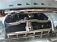
I built the kit, and delta-connected the three-phase motor's windings as suggested. I needed a pulley with a groove deep enough to take both A and B section belts, because I'd be mucking around with both 6V and 12V generators. I discovered a piece of wooden kitchen benchtop, drilled a 3/4" hole in it, filed the keyway by hand, and drove it onto the motor's shaft. Now - how to true it up and cut the groove? I figured I would G-clamp the motor onto the bed of my father's wood lathe and turn the groove into the pulley. Much sawdust later, job done. I mounted the motor onto another piece of benchtop, which I drilled to take voltage regulators. A couple of generator mounting brackets and some 8 mm dia rod, cut to length and tapped 5/16" UNF, with 8 mm ID aluminium tube cut to size, allowed me to mount the generators. I attached the top generator bracket to the motor via some angle.

Image

With this setup I was able to test generators and adjust regulators; but providing a suitable load was difficult - a hand-held 12V 50W halogen lamp was about the best I could do easily; and for 6V systems it didn't draw anywhere near enough current. Something better is needed.

So what I want is a constant-current, switchable load. Constant current? That's so that it'll pull the same current with a 6V generator as with a 12V one. With loads of 1, 2, 2, 5, 10 and 20 amps I can set any current from zero to 40 A in 1 A steps, and I don't need an ammeter. Whereas in your old-school lamp bank or resistive load, the current isn't in nice multiples of amps, so an ammeter is required. And the poor switches have to handle the full load current. There are better ways of doing things . . .

Rob
ardiesse
Posts: 1091
Joined: Thu Jan 19, 2017 9:57 am
State: NSW
Location: Sydney

Re: a test setup for generators

Post by ardiesse »

Warning - electronics tutorial follows.

A voltage regulator IC takes an input voltage and "cuts it down" to make a precise output voltage. If you connect a resistor to the output, the resistor draws a constant current, because the output voltage is constant. Now for the subtle bit: "seen" from the input, the regulator and resistor draw the same current, regardless of the input voltage. Constant current draw independent of supply voltage is exactly the property I want. And these days, voltage regulators come with a whole lot of "smarts" built-in: high output current, overload protection, and external control.

Micrel makes a family of regulators with 1.26 V output, high output current, and external enable. To make a 1 A load, connect 1.26 ohms between the output and ground.

Image

For 2 A, the resistor is 0.63 ohms, and for 5 A, 0.252 ohms. The main problem is not in coping with the current, but getting the heat out of components. For the higher current loads, the resistor dissipates a lot of heat, and so does the regulator. A big heatsink becomes mandatory. And I need a way of boosting the current without letting the smoke out.

You can "keep the smoke in" with a big power transistor and a low-value resistor. Put the resistor in series with the regulator's output, and connect the transistor across the regulator. The resistor senses the current drawn by the regulator. When the current rises to a certain value, the transistor turns "on" and bypasses the regulator. The regulator is still in control of the situation and holds the voltage across the load constant, it's just that most of the load current now flows through the transistor. In mucking around with this arrangement, I found I needed one booster transistor for every 2 A of load current, thus two for the 5 A load, four for the 10 A load, and eight for the 20 A load. When connecting the transistors in parallel, I needed a half-ohm resistor, one per transistor, to make them share the load equally.

Image

Now came the time to raid the parts bin at work. I had stacks of Jaycar heatsinks left over from a previous project. They come in two halves, and assemble onto an 80 mm fan. At 40 A and 14 V, the load will be dissipating 560 W. This'll place serious demands on the cooling fan. I laboriously mounted the components onto the heatsinks and point-to-point wired the electronics, just like in a valve guitar amp. And then a colleague took a glance at my work and said, "nice job, but it'll work for about half an hour until the PVC insulation goes soft and you get short-circuits." And so I completely rewired it with Teflon-insulated wire.

The 1,2,5 and 10-amp loads worked perfectly. The 20 A load was a bit flaky and would only pull 20 A at some voltages and not at others. And then I could change its behaviour by waving my hands over the circuit. That's the classic symptom of radio-frequency oscillations. In situations like this, the data sheet recommends a bypass capacitor on the voltage regulator's output pin.

The final touch was to make covers for the unit, which double as cooling ducts. It was not much trouble to bend them up out of sheet metal. And the sheet-metal worker at work is a genius at TIG-welding thin aluminium.

After having done the design and assembly work on the sly as a "foreign order", a colleague needed an electronic load for testing power supplies. Commercial electronic loads all have microprocessors in them and generate radio interference. Mine is purely analog, and doesn't produce interference. So I am now in the curious situation of having a foreign order elevated to "official" status.

Once we had measured the output noise of the power supplies for the new ultra-wideband Parkes receiver, I gave the electronic load a test run with my FX's Delco generator, which I thought was misbehaving. At 20 A load, the generator worked fine. But when I switched the 20 A load off, there was a "cough", and a puff of smoke came out of the heatsinks. The cooling fan didn't appreciate the voltage spike, and promptly blew up. Some more work is needed . . .

I am pleased to offer a generator testing and rebuild service, and I can set up voltage regulators too. One thing I can't do, though, is armature rewinds.

Rob
User avatar
59wagon
Posts: 645
Joined: Sun Jul 27, 2014 11:40 am
State: WA
Location: Shoalwater, WA

Re: a test setup for generators

Post by 59wagon »

Phew! Nice work Rob. Sounds compla-micated with lotsa research and testing gone into this. Thanks for offering the service 👍👍👍

Cheers,

John
User avatar
Errol62
Posts: 9879
Joined: Sat Dec 06, 2014 2:44 pm
State: SA
Location: Adelaide

Re: a test setup for generators

Post by Errol62 »

I did my best to follow it. Phew! Putting all that together and nutting it out, and then documenting it all, that’s amazing Rob. Just need to set up over internet protocol so I can take advantage of your kind offer. I’ve got a few generators rattling around the front yard I’d love to get tested by your unit.
Cheers
Clay


Sent from my iPad using Tapatalk
getting my FB ute on the road
EK van on rotisserie
ardiesse
Posts: 1091
Joined: Thu Jan 19, 2017 9:57 am
State: NSW
Location: Sydney

Re: a test setup for generators

Post by ardiesse »

Definitely need some form of overvoltage protection. Adjusting the current limit on a regulator, I made the fatal error of switching off the 20-A load with the generator charging, and popped the 1-A load. Didn't know ceramic wirewound resistors could glow red, but they do.

(Thinks - an overvoltage enable that switches on the 5-A or 10-A load when the voltage exceeds, say 18V, should do the trick)

So I went back to the old-school method of car battery, ammeter, and holding the voltage regulator contacts closed to adjust the current limit.

Rob
In the Shed
Posts: 1907
Joined: Wed May 16, 2012 10:18 pm
State: SA
Location: South Australia

Re: a test setup for generators

Post by In the Shed »

Nice work Dr Rob :thumbsup:

Reading this I had a picture in my mind of you wearing a white dust coat working away late into the night in your shed with a chalk board about 20 feet wide by 10 feet high running many calculations before you moved to the construction then test phase! Who ever said these old bangers were simple?

Keep it up.

Regards
Stephen
A day in the shed beats a day at work!
ardiesse
Posts: 1091
Joined: Thu Jan 19, 2017 9:57 am
State: NSW
Location: Sydney

Re: a test setup for generators

Post by ardiesse »

Stephen,

You're pretty close to the mark. Except that I doodled it all out on A4 printer paper at work in my "spare time".
But the humble voltage regulator does with three relays the same job as a switch-mode power supply controller integrated circuit. I am amazed what the engineers of yore achieved without electronics.

Rob
User avatar
Harv
Posts: 5105
Joined: Mon Oct 08, 2007 2:00 pm
State: NSW
Location: Sydney, Australia

Re: a test setup for generators

Post by Harv »

Very,very cool Rob 8) .

I've been slowly getting some electrical bits together, as I need to learn more about starters and generators (I also need to get the magneto test bench project going once the EK wagon is on the road). Worked out my little SuperCheap ammeter was not going to cut the mustard, so bought a decent Fluke clamp meter. Purchased a Vane condenser checker... can probably do this with the Fluke, but the Vane is neater:
vane.JPG
vane.JPG (725.64 KiB) Viewed 753 times
I managed to pick up a VRA made by The Auto Lab Co in Sydney:
main.JPG
main.JPG (783.19 KiB) Viewed 753 times
closeup.JPG
closeup.JPG (688.18 KiB) Viewed 753 times
It came with the box-of-snakes wiring shown in the photo above. The snakes were horribly perished, though when I opened the unit the insides were in great nick. I replaced the red and green wires, then got a bit worried as I didn't fully understand how the internals worked... my bottle of replacement Magic Smoke gets enough of a workout, so have not hooked it up to power yet. :oops: Might have to get your help at some stage please to understand this thing better. If you would like to run it alongside your test bench you are more than welcome.

Cheers,
Harv
327 Chev EK wagon, original EK ute for Number 1 Daughter, an FB sedan meth monster project and a BB/MD grey motored FED.
ardiesse
Posts: 1091
Joined: Thu Jan 19, 2017 9:57 am
State: NSW
Location: Sydney

Re: a test setup for generators

Post by ardiesse »

Harv,

I'd be glad to help re-wire the VRA box. The condenser checker looks like a nice piece of gear (but you can use a good-quality digital multimeter to the same effect).

You might have to check that the meter movements still move freely - it's a watchmaker's job to put the movements back on their pivots if the box has been dropped. The broken glass on the voltmeter won't be aiding matters either.

Rob
User avatar
thebrotherj
Posts: 660
Joined: Wed Aug 21, 2013 4:09 pm
State: NSW
Location: Sydney

Re: a test setup for generators

Post by thebrotherj »

Rob, this is all very clever and dedicated, nice work.

I might run my two EK generators up to you for checking/servicing if you were interested in taking that on?

Cheers, Joe
ardiesse
Posts: 1091
Joined: Thu Jan 19, 2017 9:57 am
State: NSW
Location: Sydney

Re: a test setup for generators

Post by ardiesse »

Joe,

No problem.

Rob
Post Reply