Hi Bus,
yes - these can be a bit tricky, like most things - we pull em apart when they stop working and sometimes can't get them back together as it would seem logical for them to work.
I had a lot of trouble when I was a kid with this ..... ended up nearly getting thrown out at a drive-in when the blasted thing (no pun intended) started to sound on it's own and I couldn't stop it - until someone showed me the fuse........
I had pulled it apart earlier in the day because of a "scraping" sound when turning the steering wheel and just couldn't get the thing back together in the order it originally came apart.......
Answers..... yes - your steering wheel has to be rock hard when the nut and lock nut are tightened - we don't want a "sloppy" steering wheel - the steering on these dear old things leaves a lot to be desired at the best of times..... let alone create any additional slop.......
The horn blowing ring must have spring in it - this is the switch.
There aren't any springs fitted to this assembly to make it return - the only "spring" is the contact ring (with holes in it) and of course - the tension spring to hold the brush in contact with the brass ring on the steering mast.
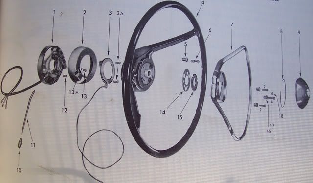
The pic below is the order and orientation of the parts you will need to refit correctly. I do understand you have the manual - but for the benefit of others watching this post - I have included this in my post.......
I note your concern with the replacement contact but feel it should not be an issue..... I don't know how skilled you are with a soldering iron, but if your old contact is not damaged, you may consider replacing the parts which don't fit with the old ones and soldering it back as an assembly.......
But..... from what I can see in your pics - it should work fine - Rare's have obviously made some modifications to the original - but from what I can see - it is all "easy fix" to manufacturing.... and should function perfectly.....
Probably one thing I would suggest you do is to smear some electically conductive lubricant onto the contact ring to prevent it wearing prematurely or indeed - scoring the ring.....
Only the brass pin is critical - it must have a smooth flat working end (face) and must fit snugly but freely into the insulator which houses it in the steering wheel hub.
The other end of this contact assembly simply makes a momentary contact with the horn switch contact (ring with holes in it) when this is deflected.
Please excuse me if I am stating what you already know but......
Your horn is permanently wired "live" on the positive side - if you short the negative terminal on the horn itself to the body - it will sound.....
Only a fuse on the fuse block isolates this positive supply to the horn (this is what stopped the cafuffle at the drive-in that night.......).
Horn operation is made by "earthing" the other side of the horn armature - this is done by pressing the horn ring or pushing in the central button (the lovely black cover).
The contact operation is made by the horn ring connecting the brown horn wire to the steering shaft through the brush (for want of a better word) contact which you are replacing.
This brush - diagram number 6 (although it looks like a brass pin with braid soldered to it and a tag at the other end) is permanently in contact with the horn contact ring (diag. # 3 )and it slides around on it as the steering wheel is turned (this is where my "scraping" sound emanated from many years back - a grooved horn contact ring......).
The actual operation contact is made by deflecting the horn switch contact (with holes in it...diag. # 14 ) by its spacer (diag. # 15 ). This, of course - is done by placing it under "load" by the horn ring or central button.....
To prevent the horn operating at all times, insulating spacers (diag. # 16 ) are fitted on the horn blowing ring mount screws. These isolate the horn ring from the steering shaft and electrically insulate any contact.
To operate the horn, the horn blowing ring (or button) is depressed, the horn switch contact is deflected by its insulator and makes contact with the steering wheel metal hub - which of course is splined to the steering shaft and this makes the electrical connection to earth.
The important bits (which most of us stuff up) are the orientation of the horn switch contact - it must be fitted as shown in the diagram.
The isolators must be positioned so that when the assembly is screwed down, they insulate the horn switch contact from any earth.
It often is the case (as was in my learning of this) that even with the parts correctly fitted, it is possible to "trap" the horn switch contact under one of the insulators as you screw down the assembly...... this is where I feel you are having problems.......
My suggestion - fit all parts so that the horn switch contact is correctly positioned and ensure that the three isolators keep this contact in place without trapping it under them as you tighten down the horn ring by its three screws.
Where I feel you have ... ummmm.... "erred..." is that you have fitted the screws and insulators incorrectly which is causing the contact to deflect under the load of your screws as you tighten them down.
You must fit the three screws through their respective isolating bushes into the horn blowing ring - then through the bakelite insulator and finally through the three larger holes in the contact ring - that allows this contact ring to deflect up and down under load from the operating ring or button.
If you screw this down through the three smaller holes - you will compress the ring and it will make permanent electrical contact with the steering shaft.......
or
if you have all this fitted correctly, if this contact ring slips under one of the insulators - the same thing will happen - you will screw it down and trap it - causing it to make permanent connection - and of course - no spring return......
If this fails - you may have a defective component which is allowing the assembly to make an earth contact - hopefully we won't have to track that down......
hope this helps, Bus....
frats,
Rosco


