The Howarth fuel injection system is an interesting cross-breed between a constant flow injector, and a carburettor. To explain the workings of the system (and why it is so different), I will start by describing a typical constant flow fuel injection system, such as those made by McGee, Kinsler, Enderle or Hilborn.
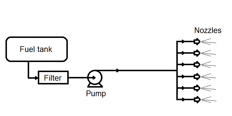
A constant flow fuel injection system assumes that the engine's fuel requirement is nearly linear i.e. that fuel flow to the engine should increase in direct proportion to engine rpm. If the engine needs 30 gallons per hour at 2,000rpm, it should then need 60 gallons per hour at 4,000rpm. To do this, the fuel injection pump is driven by the engine, and puts out increased flow at increased rpm (say 30 gallons per hour at 2,000rpm, and 60 gallons per hour at 4,000rpm). This is different to the standard grey motor fuel pump, which whilst engine driven normally changes flow very little with increased rpm. Our grey motor fuel pump puts out about 4psi, whilst a fuel injection pump is around 150psi. The constant flow injection pump draws fuel from the fuel tank through a filter to avoid clogging the injector nozzles. The pump can be belt driven off the crank, driven off the camshaft snout (through a hole in the timing cover), or driven off the distributor. As you can imagine, none of these locations is a simple bolt up job for a grey motor. Typically, the fuel pump is driven at half crankshaft speed (this is one reason that the camshaft or distributor are handy places to run it from, as they both run at half crank speed).
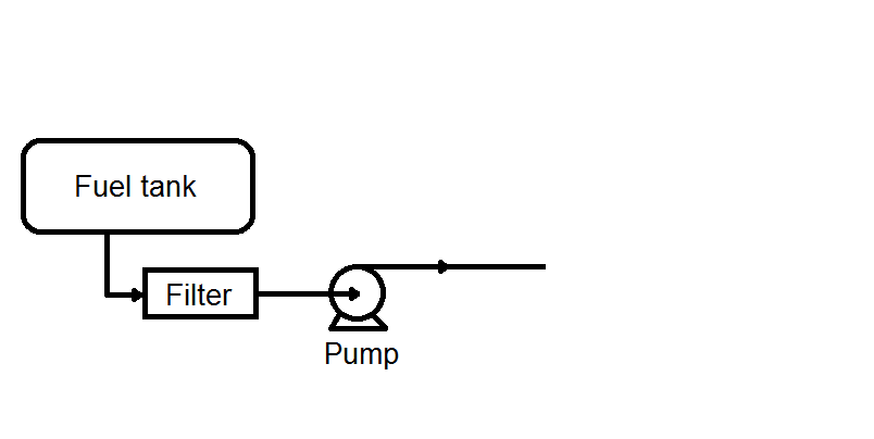
The fuel injection pump is connected by lines to each individual injector. Inside the injector is a simple spray nozzle, similar to the water misters that you can buy in Bunnings to use on a garden irrigation system. The term “constant flow” refers to the fact that the whenever the engine is running, the fuel pump is spinning, and fuel is being squirted through the nozzles. If the inlet valves are open, the fuel flows into the cylinder head and thence into the cylinder. If the inlet valves are shut… too bad, the fuel still flows. This is different to our grey motor carburettor, where fuel is only “sucked out” when the inlet valves are open. It is also different to a timed injection system (for example that used in Triumph’s PI injection). A timed injection system only squirts fuel into the injector when the inlet valves are open and the cylinder is ready to receive it.
So for our constant injection system we now have a fuel pump that varies with engine speed, and some squirters to spray the fuel into the cylinder head. We now need to control the amount of fuel that the engine gets. In our grey motor, we would normally open and shut off the air supply to the carburettor. This lets the engine suck in more or less air, and hence suck in more or less fuel. For our constant flow injection set, we instead use a valve (often called a barrel valve) to turn the fuel on and off. The barrel valve is connected to the throttle butterflies, which let more or less air in. In this case, we are controlling both air flow and fuel flow at the same time (whereas the standard grey motor is controlling only air, and fuel is resultant).
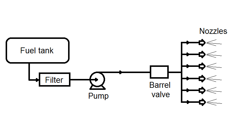
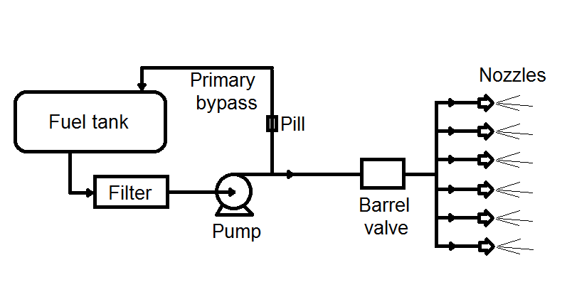
The barrel valve however is a pretty rough animal. It reduces fuel flow for idle, and about the first third of throttle opening. After that, it loses control and is wide open. This sounds pretty rough, but bear in mind that most mechanically injected cars have only two speeds – idle and flat out. If our barrel valve is wide open, the question then becomes how we set the air/fuel ratio. This is done by using a fuel pump that is too big for the engine’s needs. The excess fuel is recycled back to the fuel tank by a primary bypass line. The bypass line contains a poppet valve that blocks off any recycling when pump speed (and pressure) is very low (for example when starting the engine). The amount of fuel recycled back to the tank is determined by a restriction orifice in the return line. The orifices are changeable (like a grey motor main jet), and are referred to as “pills”. A larger pill will recycle more fuel back to the tank, and let less fuel flow to the engine (leaner). A smaller pill will recycle less fuel back to the tank, and let more fuel flow to the engine (richer). By examining how the engine performs at full noise, we can see how much more (or less) fuel it needs to get a decent fuel/air mixture, and can thus choose a smaller (or larger) pill.
Most constant flow injection sets also use a secondary bypass. When the throttle is closed (for example when cornering during speedway), less fuel is needed. A spring-loaded poppet valve (the secondary bypass) opens, recycling fuel to the tank. The secondary bypass usually only operates in the first 1/3 of throttle travel.
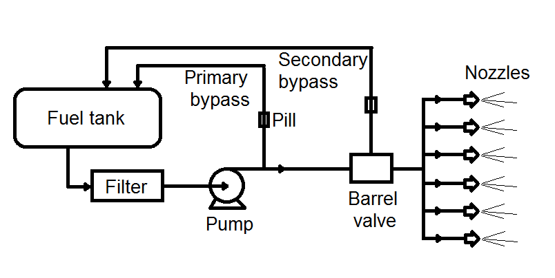
Some more fancy injection systems also use a high-speed bypass. When the engine is really singing, it can overfuel the engine due to the pump spinning so fast. An additional spring-loaded poppet valve thus opens at high fuel pressure, allowing fuel to recycle back to the tank.
So how is the Howarth injection system different from this?
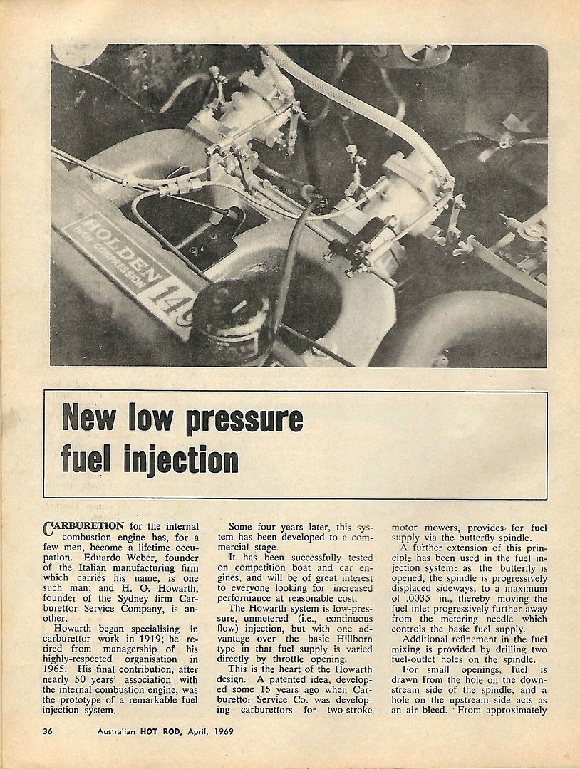
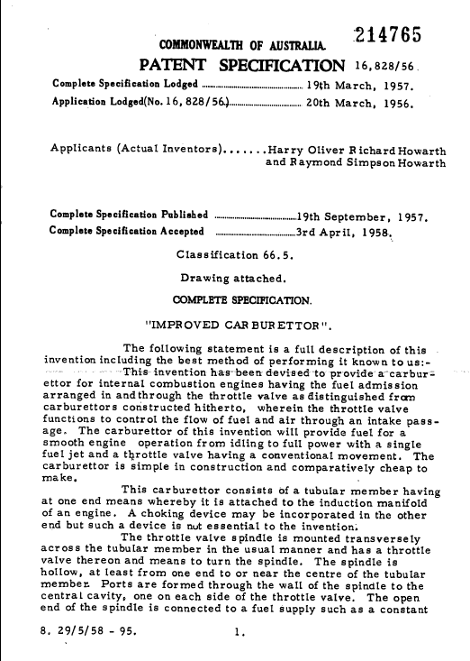
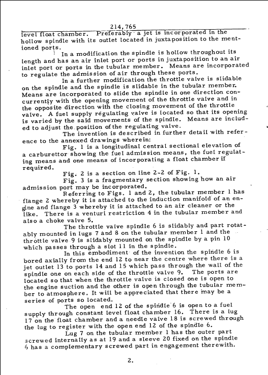
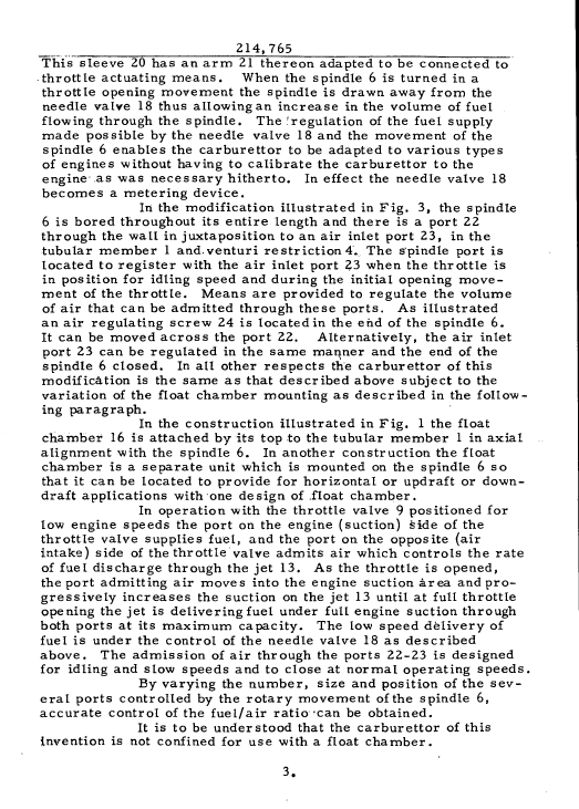
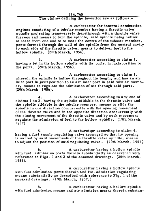
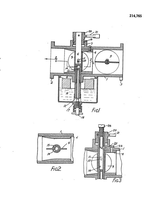
As noted above, the Howarth fuel injector concept is an interesting cross-breed between a constant flow injector, and a carburettor. The concept had it’s origins in Howarth’s improvements to two-stroke motor carburetion. The images below show the original patent raised by Howarth for the concept.
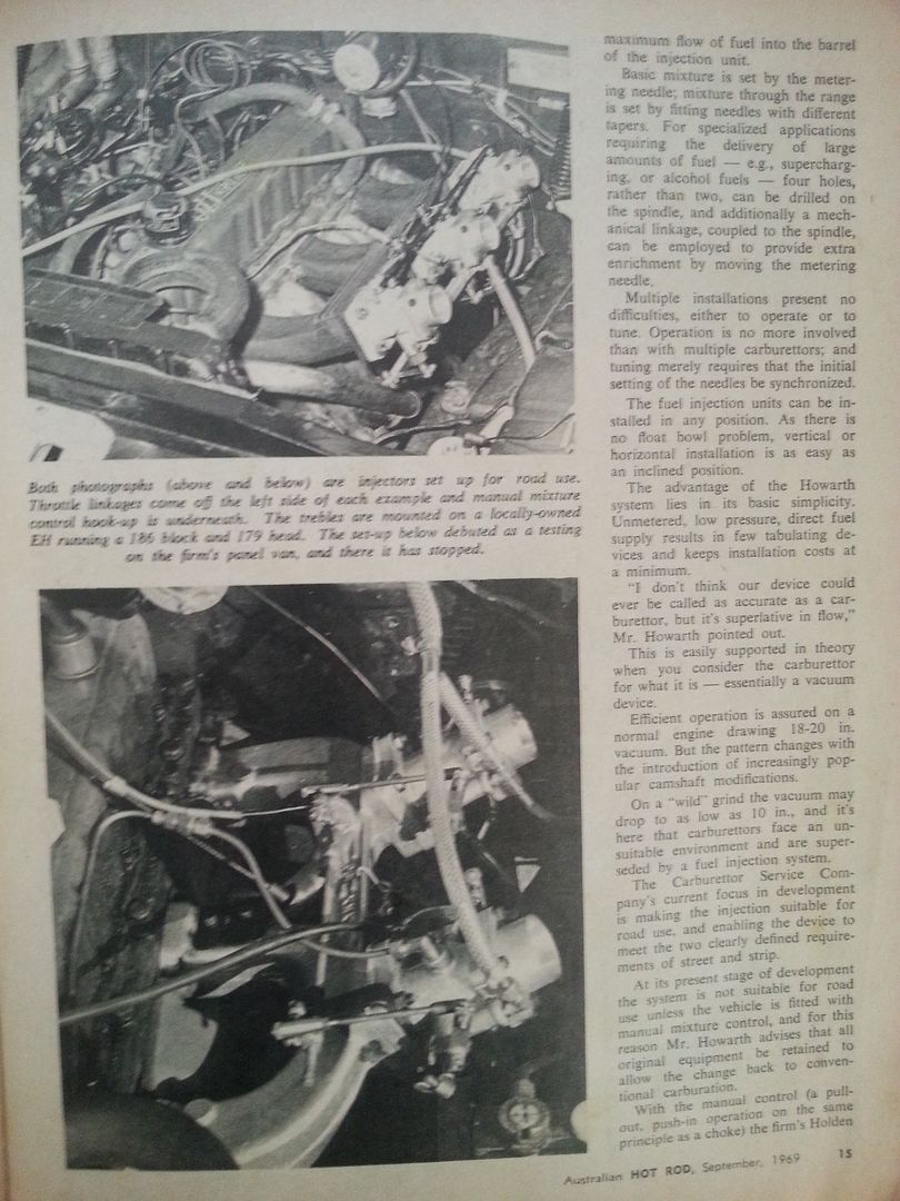
Unlike a typical constant flow system, the Howarth injection system does not use a high pressure injection pump. It relies on the standard grey motor fuel pump, putting out fuel at 1.5 to 4.5 psi. Fuel is plumbed from the fuel pump discharge through to the injector body. Photos of the period injectors show that clear PVC tube was typically used. A fuel filter in the line is not a bad idea, though the Howarth fuel injectors do not have the same blockage risks as the fine-bore constant flow injection nozzles. The Howarth injector bodies have three tappings to allow fuel in, allowing a choice of 180 degrees of piping orientation. The tappings can also be used to piggyback fuel from one injector body to another. Unlike a typical constant flow system, there is no recycle flow back to the fuel tank with the Howarth injector.
Inside the injector are a number of components that control the flow of fuel. The drawing below shows a cross section of the injector, approximately to scale. In the following text I will try to use the same language as the magazine articles shown above.
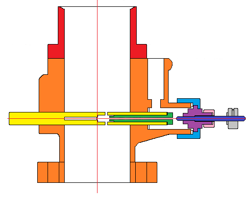
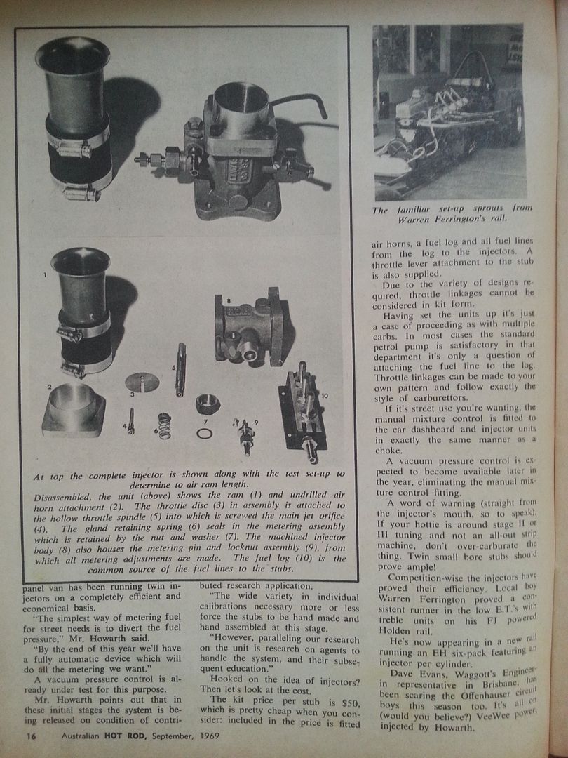
The red colour shows the air horn attachment, which bolts to the orange injector body. The hollow throttle spindle, shown in yellow, screws into the injector body. This screw connection is important, as it allows the spindle to move laterally – more on this later. I have not shown the throttle disc (butterfly) in this drawing for simplicity. Screwed into the throttle spindle is the main jet orifice, shown in green. To the right of the drawing are the metering pin and locknut assembly, shown in dark blue and purple respectively. The metering pin and locknut assembly are held into the injector body with a retaining nut, shown in pale blue. The metering pin and locknut assembly is sealed off using a gland retaining nut, shown in pink. To the far right of the drawing is the metering pin adjustment knob, shown in grey.
The photo below shows the internals lined out:
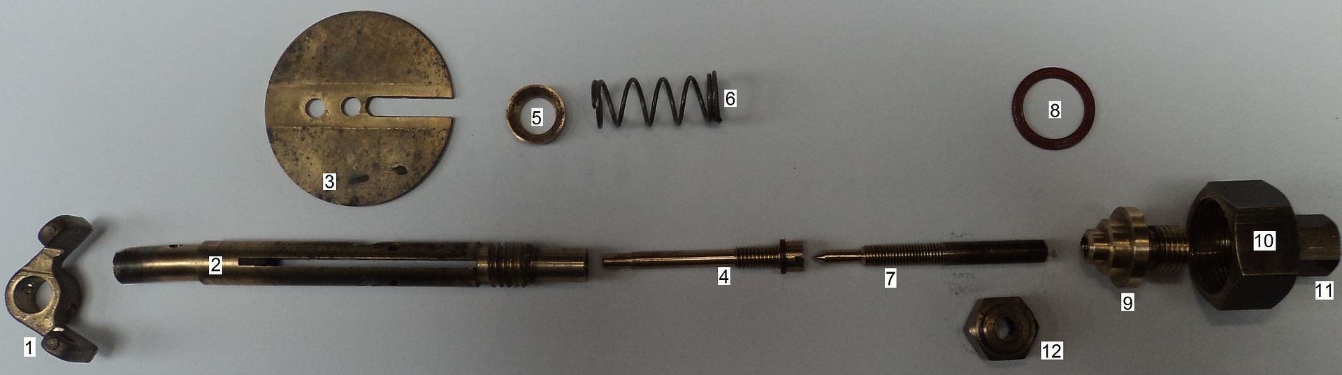
Item number 1 is a brass throttle stop that mounts to the end of the throttle spindle. This limits throttle spindle rotation to 90º. It also has a set screw and spring (not shown) that allows the throttle plates to be cracked open to set idle speed. Item number 2 is the brass throttle spindle. Item number 3 is the throttle disc. Note the groove (which allows fuel to flow along the hollow throttle spindle), and the two holes (which allows fuel to flow out the upstream and downstream side of the throttle disc). Item number 4 is main jet orifice, shown here with it’s fibre gasket attached. Item number 5 is a gland follower, whilst item 6 is the associated gland follower spring. Item 7 is the metering pin, with the associated locknut labelled as item 9. Item 8 is a large fibre washer that seals against the injector body. Item 10 is a gland retaining nut, whilst item 11 is the metering pin adjustment knob.
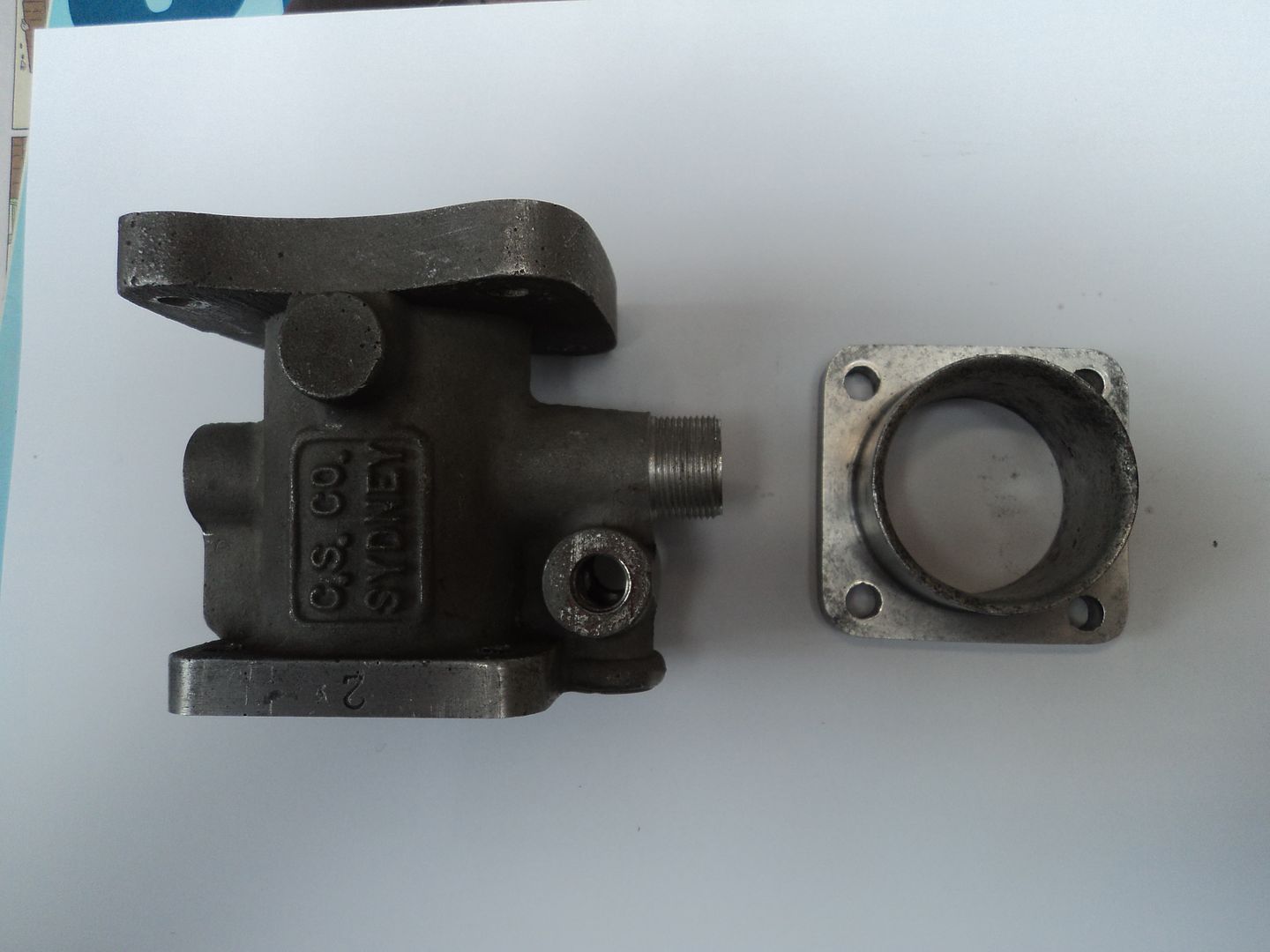
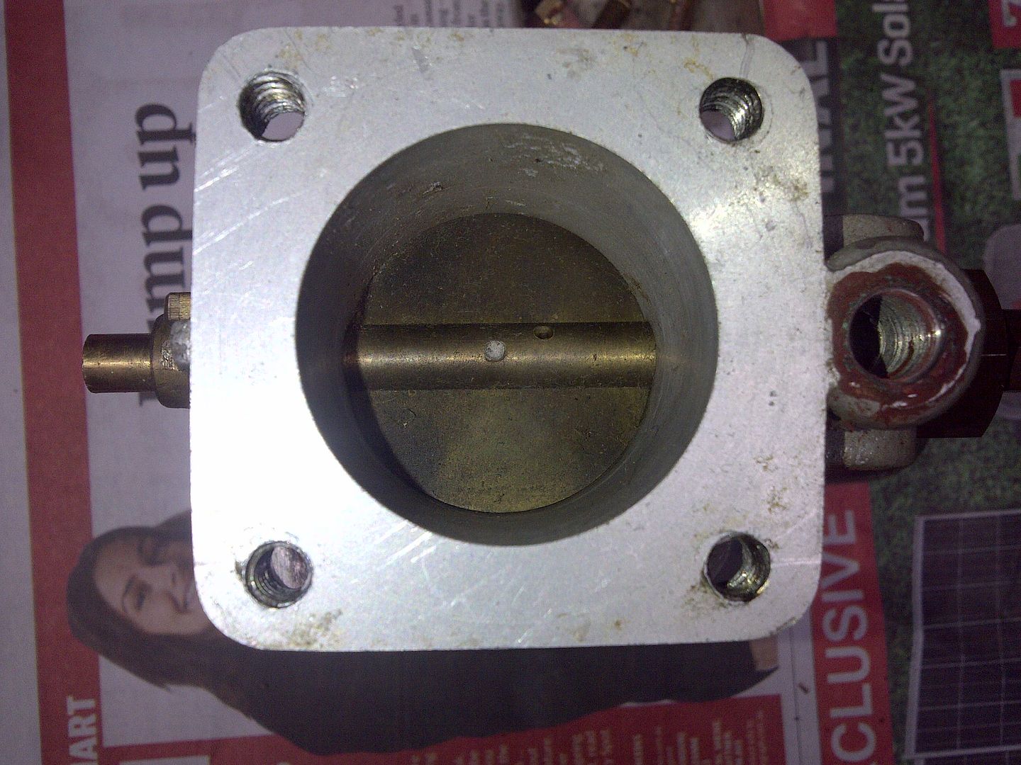
The injector body and air horn attachment are shown below:
Note that there are a number of seals which I have not described very well above. The drawing below highlights these:
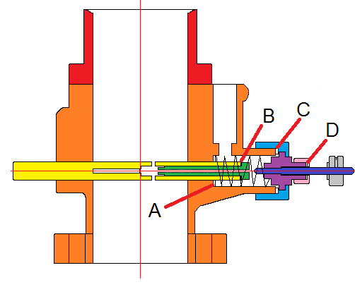
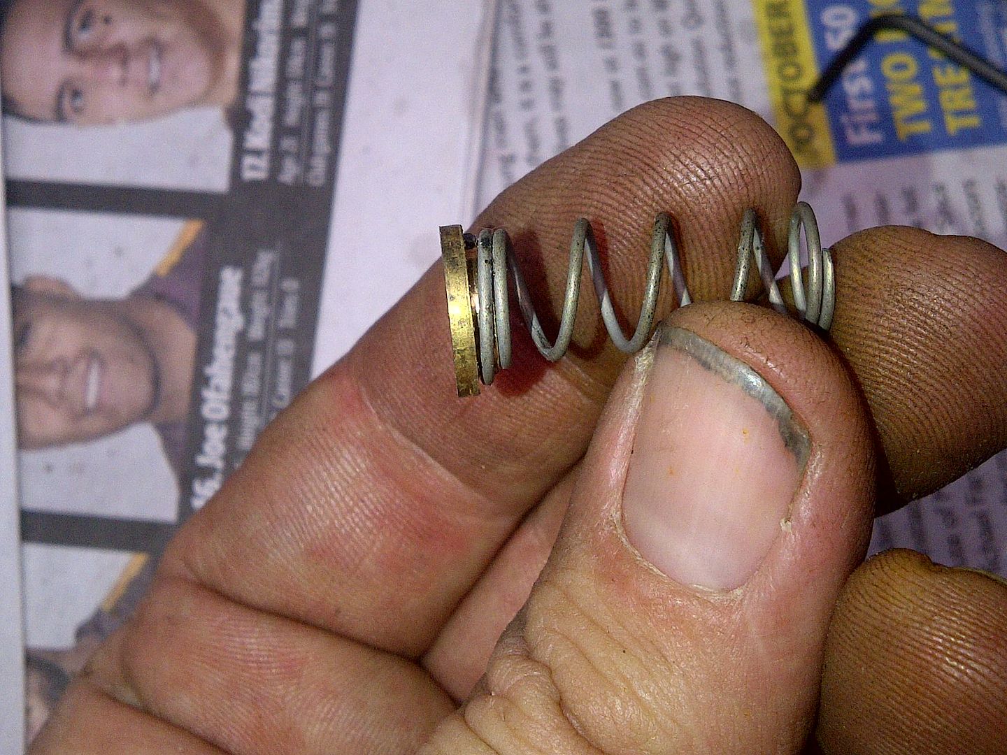
Location A is a fibre gland which seals the throttle spindle to the injector body, forcing fuel through the centre of the hollow throttle. This gland is held in place with a follower and retaining spring. I did not show the spring on the earlier diagram, but is can be seen zigzagging in the drawing above. The spring and follower sits in the fuel inlet path, but provides little obstruction. The spring and follower are shown below:
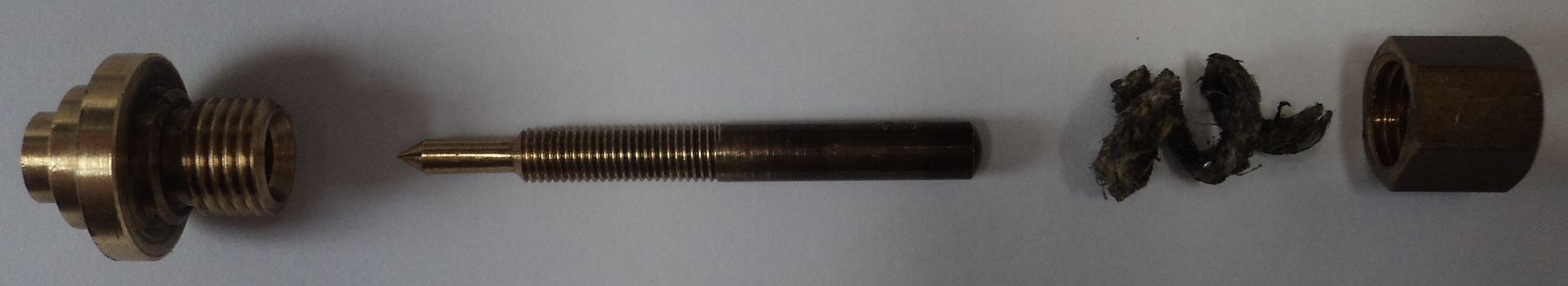
Returning to the diagram above, Location B is a fine fibre gasket that seals the main jet orifice to the throttle spindle. This washer prevents unmetered fuel bypassing the main jet orifice. Location C is a larger fibre gasket that seals the metering pin and locknut assembly retaining nut to the injector body. This washer prevents fuel leaking from the injector body to the outside world. Location D is a length of fibre packing gland that seals the gland retaining nut to the locknut assembly. It prevents fuel travelling along the metering pin threads and leaking to the outside world. A photo of the gland is shown below:
In the diagram below I have recoloured the air horn attachment orange (the same as the main body), and have used red to show the fuel flow path:
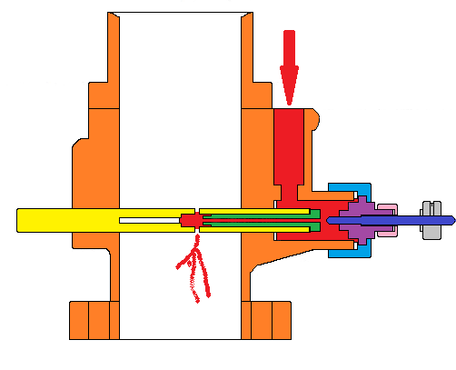
Fuel from the grey motor fuel pump flows in through the top right of the diagram. On entering the injector body, the fuel flows into a chamber. From the chamber, the fuel flows to the left through the main jet orifice (shown in green above). The main jet orifice looks suspiciously like a Stromberg idle tube. The internal diameter of the main jet orifice determines (roughly) how much fuel will flow through the injector. This means that for a given engine, you can change the main jet orifice to size the injector (or injectors) to the engine’s needs. For example, if running two injectors on a grey motor, the main jet orifice will be larger than if three injectors were used. As a rough guide, the main jet orifices running on my injection set on a grey motor are 0.055” internal diameter (and as an aside, 1.635” long).
With the rough fuel metering taken care of, the engine needs a way of fine tuning the metering. As the fuel flows into the end of the main jet orifice, it passes the metering pin (shown in dark blue above). The metering pin acts as a needle valve, with the end of the main jet orifice acting as the valve seat. The metering pin can be moved closer to (or further away from) the main jet orifice by turning the metering pin adjustment knob. This makes the metering pin screw into/out of the threaded metering pin locknut, shown in purple above. Screwing the metering pin in will restrict the flow of fuel (leaner), screwing the pin out increases the flow of fuel (richer). The graph below shows the way that the flow responds as the metering pin is opened.
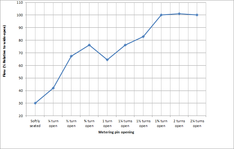
Excluding the outlier at 1 turn open, the data is relatively linear up to 1¾ turns open (i.e. if you are tuning a Howarth injection set, only the first 1¾ turns of the metering pin are useful). Some Howarth injectors are tuned, and then left with the metering pin in a fixed opening. However, as we noted above, some of the Howarth sets historically have had two linkages – one for throttle and one for mixture. The mixture linkage screws the metering pin in and out. This allows the mixture to be controlled from inside the cabin. It’s a fair assumption that the linkage could get perhaps 3/8 to 3/4 of a turn out of the spindle, limited by the mechanics of the linkage arms. With this range of travel, the fuel flow through the injector can be changed by around 35%. That’s not too bad… it’s the equivalent range change of about 10 Stromberg carburettor fixed main metering jets (say jetting from 0.040” through to 0.050”).
Having been accurately metered, the fuel flows to the left from the main jet orifice and through the hollow throttle spindle. Near the centre of the throttle spindle, the fuel can flow out of the throttle spindle and into the air stream being sucked through the air horn attachment and injector body. There are two holes drilled through the throttle disc (butterfly) to allow this – the first on the downstream side of the disc, and the second on the upstream side of the disc. When the throttle disc is nearly closed (idle), the throttle disc has a pressure drop equal to engine vacuum – about 18”Hg or 9½ psi. This pressure drop is sufficient to prevent fuel flowing from the upstream hole of the disc (i.e. the inrushing air stops the upstream hole flowing). The air pressure differential (~9psi) is higher than the fuel pressure inside the throttle spindle (~3½ psi from our grey motor fuel pump). This allows some air to flow into the upstream hole, mixing with the fuel inside the hollow throttle spindle, and acting as an air bleed. This air flow will help with fuel emulsion (and vapourisation) at low engine speeds. On the downstream side of the disc however both fuel and any emulsified air will flow out, into the injector body and hence into the engine. As the throttle is opened, the throttle disc turns, and the vacuum across the throttle disc decreases. At some point the vacuum is low enough that the pressure drop across the disc is less than the fuel pressure in the throttle spindle. At that point, fuel will begin to flow from the upstream hole (and continue to flow from the downstream hole). In short, at idle and part throttle only the downstream hole flows, and as the throttle is opened more both holes begin to flow. As a rough guide, the throttle disc holes running on my injection set on a grey motor are 0.055” and 0.088” diameter. The upstream hole can be seen in the photo below:
Finally, one of the very, very different aspects of the Howarth injectors is that the fuel metering changes with throttle position. As we noted above, fuel metering is richened (more fuel flow) by moving the metering pin (dark blue in the diagram below) away from (to the right in the diagram below) the main jet orifice (green in the diagram below).
[/URL
This metering is independent of throttle position. However, the throttle spindle on the Howarth injector is threaded, and screws into the injector body. The thread can be seen indicated by the green arrow on the photo below:
[URL=http://s929.photobucket.com/user/V8EKwagon/media/Howarth%20injection%20spindle%20movement_zpsjto5cswc.jpg.html]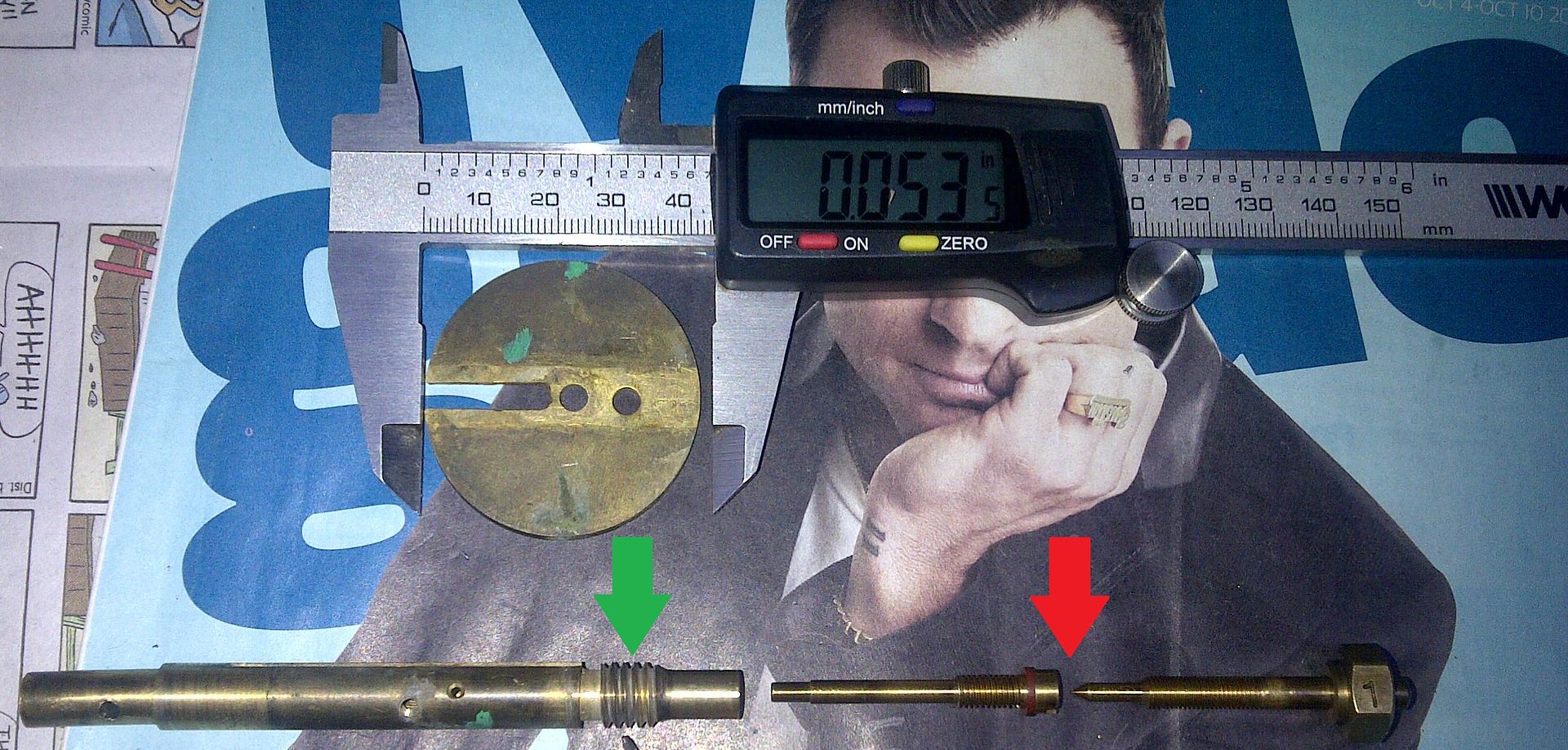
As the throttle is opened and the spindle rotates, the spindle screws itself out of the injector body. This moves the throttle disc sideways in the injector bore. This is achievable because whilst the injector bore is circular, the throttle disc is not – as shown in the photo above, the throttle disc is ovoid, with a difference in diameters of some 0.053”. The magazine articles shown above indicate that the throttle spindle can move laterally as much as 0.035”. As a rough guide, the throttle spindle on my injection set on a grey motor moves laterally some 0.018”. The movement of the throttle spindle means that the main jet orifice (screwed into the throttle spindle) moves away from the fixed metering pin. This opens up the gap between them, indicated by the red arrow in the photo above, richening the mixture. In short, as the throttle is opened, the throttle spindle moves sideways, allowing more fuel to flow to the injector.
Cheers,
Harv (deputy apprentice Howarth injection reverse engineer)
 ). A bit like the magneto thread, I suspect I will get carried away and this will become a general grey motor injection thread (maybe Olbis and McGee…kinda like the magneto thread now has a variety of ignition types in it).