Page 28 of 76
Posted: Tue Mar 03, 2009 10:50 pm
by V8EK4us
Posted: Tue Mar 03, 2009 11:38 pm
by ozfueler
You are a 'freak' Garry, but a helluva talented one, and also a very generous one.
The parts you sent prior to christmas worked a treat, thanks mate.
Looking forward to catching up at Bendigo, I owe you a couple or more cold ones.
The car is looking AWESOME and the posts are eagerly awaited, can't wait to see it in the flesh!.
Steve...
Posted: Wed Mar 04, 2009 12:34 am
by J
wanna do mine next?
pleeeeeeeeeeeeeeeeeeeease

u got an engineer coming to look at this during the build or are you just going to get one to come at the end?
Posted: Wed Mar 04, 2009 8:29 pm
by V8EK4us
Blacky - 48hrs in a day


Steve (ozfueler) ....... you have a deal!
my70wg - yes there is something in the water ....... alcohol
J - maaaate, always in touch with the Engineer as there have been some changes as she has progressed, it's all good, can't leave these things to the last minute or

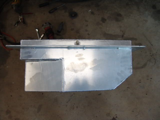
Designed the fuel tank and had our Gun TIG welder at work (Michael) weld it up while I've been doing body mods.
Tank ended up 95lts and has 2 baffles setup inside it to stop fuel pressure under acceleration from possibly leaking from the filler as it is still in the original position. There is a baffle to also stop acceleration starving the motor, basically the "box" under the tank is a "swirl pot", the tank bottom plate has a 40mm hole in it and the pickup is run into the "swirl pot", there is a full width baffle running across the tank directly behind the "swirl pot" so under hard acceleration there will always be sufficient fuel "trapped" to keep the chevy going.
Still have to finish polishing it all yet

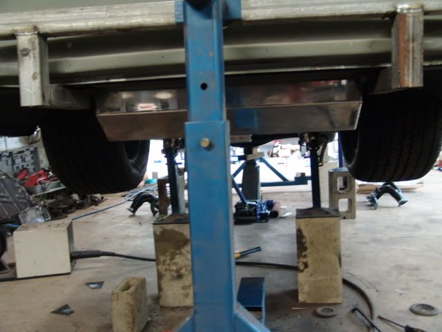
Underside of tank, angled sections are for exhaust clearance:
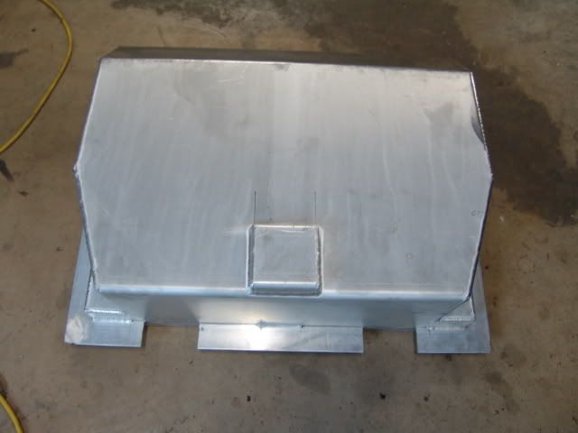
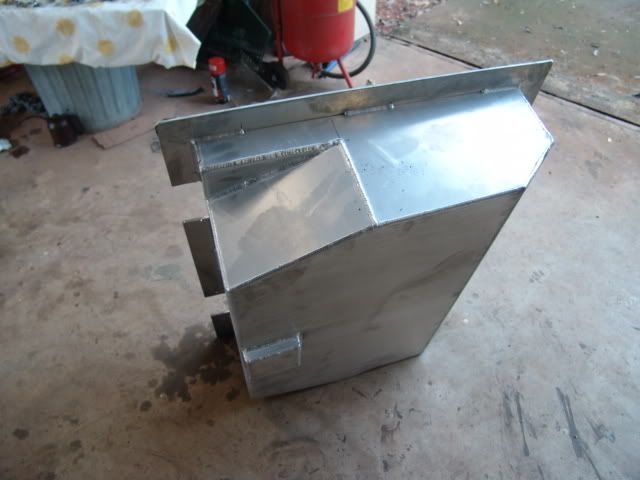
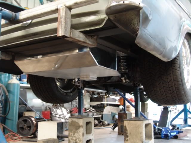
Side profile, tank main bottom plate is tapered so it matches the angle of the lower guard.
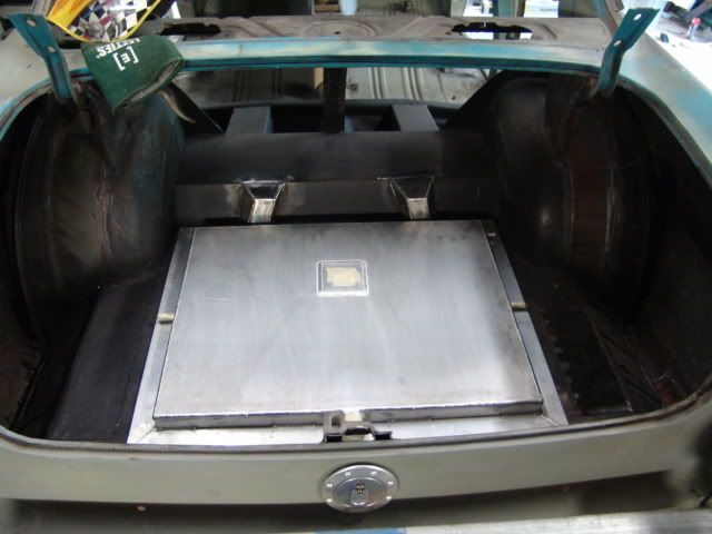
Tank in position, false floor will cover it all, I will lose about 65mm depth in the boot, I set it above floor so it wouldn't hang too low:
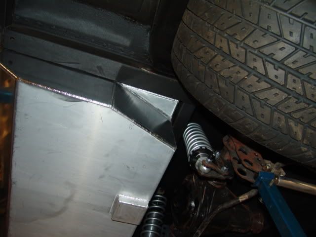
Shot showing clearance for exhaust, the "swirl pot" will also be drilled and tapped for a drain bung:
External shots:
Posted: Wed Mar 04, 2009 9:25 pm
by my70wg
Posted: Wed Mar 04, 2009 9:53 pm
by V8EK4us
Posted: Wed Mar 04, 2009 10:55 pm
by Harko
this is getting exciting

Love the tank , although its race car based it looks like there is effort gone into it . Hope you kept the plans

Posted: Wed Mar 04, 2009 11:01 pm
by ekturbo
Nice bud, am looking at tubbing mine soon but I have been told modifying the chassis and the wheel sizes I want are illegal in qld.Are the sedans and wagons different setup regarding rear chassis and wheel wells? I can`t tub mine I think without installing a new rear chassis. You have done a nice job, gonna be one helluva tough car,even if it`s a v8

Posted: Thu Mar 05, 2009 12:10 pm
by V8EK4us
Posted: Thu Mar 05, 2009 5:01 pm
by NoMAD
Posted: Thu Mar 05, 2009 5:50 pm
by J
thats the sexiest fuel tank ive ever seen
Posted: Fri Mar 06, 2009 9:56 pm
by oldnek
Awesome work there Gary, definitely no need for inspiration from us. She's gonna be one heck of a build.
Regards John
Posted: Sat Mar 07, 2009 12:40 pm
by V8EK4us
Thanks for the posts Nomad, J and John!
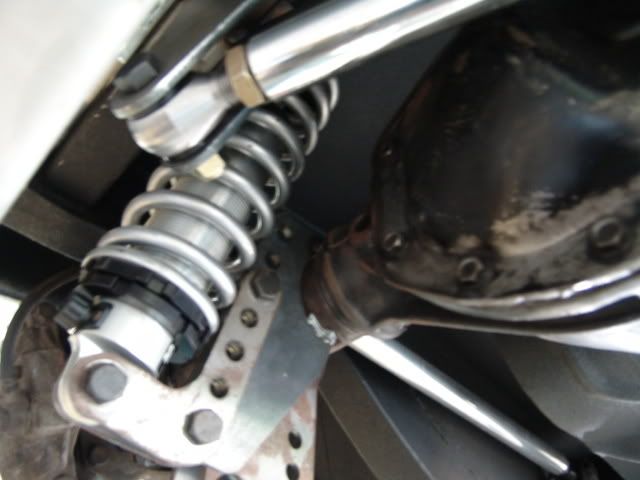
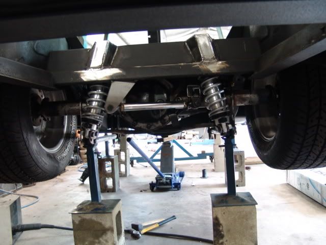
Due to needing the fuel tank capacity I cannot fit the watts link in
. With the way the exhaust, coilovers etc are it is also not practical to run a side to side full length Panard Rod. I drew a sketch on the floor with reference marks for the settled ride height at 0.0mm to max extension and max' compression with different Panard lengths to determine the shortest practical Panard I could run and still retain minimal side to side movement of the diff during suspension travel. End result was 350mm Panard length with a maximum diff movement (to the left) of 4.5mm at full compression or full extension. As a comarison a 500mm Panard would have only reduced the movement by 1.5mm on full travel. Main advantage is that the Panard is Rose jointed with left and right hand threads which means I can set the wheel to guard clearance to be exactly the same each side by loosening the lock nuts on the rose joints and turning the Panard clockwise or anti clockwise which will shorten or lengthen the Panard Rod, once the lock nuts are tight the wheels cannot move side to side (other than the 0.0mm to 4.5mm to the left during suspension travel).
At settle ride height the panard is setup parallel with the diff, at full compression/bottomed out on bump rubbers the diff will move 4.5mm to the passenger side which is not worth worrying about as you get more side to side movement than that on most Leaf spring suspension setups due to the bushes and shackles and these move both ways (left and right)

.
Posted: Sat Mar 07, 2009 1:27 pm
by EK283
Gary,
Just food for thought, I run a watts link on my race car and it is held from the body in the middle and runs out to the diff ends. Just looking at your pic it looks as if it could fit. Although like you said if the tanks in the way then no go, Bummer.
Regards Greg
Posted: Sat Mar 07, 2009 4:00 pm
by V8EK4us
EK283 wrote:Gary,
Just food for thought, I run a watts link on my race car and it is held from the body in the middle and runs out to the diff ends. Just looking at your pic it looks as if it could fit. Although like you said if the tanks in the way then no go, Bummer.
Regards Greg
Thanks Greg, I did consider that but there are a number of things to consider (easy when I'm sitting under the car looking at it
).
The watts link could mount off the chassis in the centre of the car, the problems are anchoring the rod ends:
1/ Nothing can protrude past the coilovers as this area is for the exhaust and there is only enough room for the exhaust each side with acceptable clearance.
2/ The 4 link mounts are directly next too the coilover mounts (on the outside).
3/ Because the diff is so short the coilover shock bracket on the left side is virtually at the join of the axle tube and diff centre housing which leaves no room at all for a Watts link bracket for the rod end.
I could make brackets that are twisted and bent (would look like "Steady Eddie" holding the rodend
) to get around exhausts and shocks but they would need to be very long which causes strength concerns and it would not look right, during "normal road use and suspension travel the diff will move about 2mm so I figured that it's not worth making it look "like a dogs breakfast" to save 2mm.
It's getting a bit squeezy under there
This is the gap for the exhaust to come through:
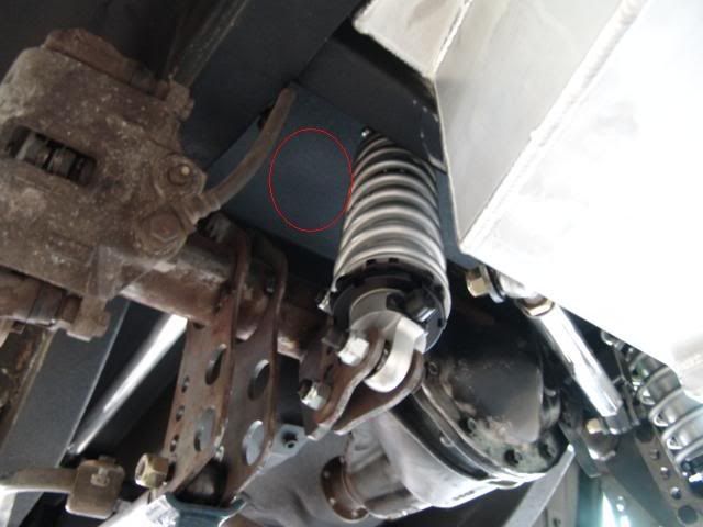
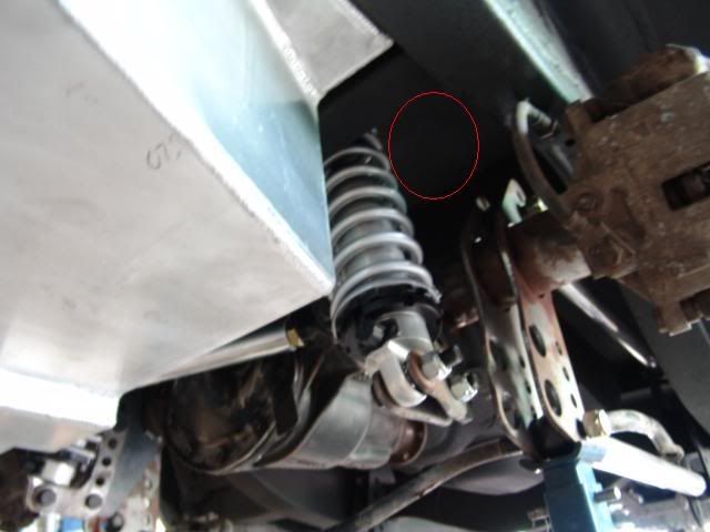
Coilover bracket position: