Harv's Norman supercharger thread

Includes fuel system, cooling system and exhaust.

Moderators: reidy, Blacky

Post Reply
User avatar
Harv
Posts: 5043
Joined: Mon Oct 08, 2007 2:00 pm
State: NSW
Location: Sydney, Australia

Re: Harv's Norman supercharger thread

Post by Harv »

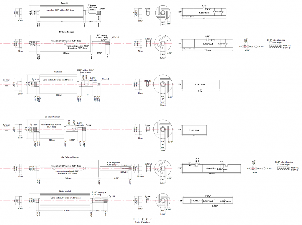
A quick update on some of the measuring that has been going on. Attached below is an update of the rotor drawing for the various Norman superchargers. The aim by the end is to end up with a decent set of drawings of the entire setup (rotors, casings, manifolds and drives). This should be useful for the next guy trying to fabricate manifolds, or seeing whether a given Norman will fit under the bonnet.

Image

Apologies again for the thread jumping around a bit - that's the price you pay for doing this as a thread rather than a Guide.

Cheers,
Harv (deputy apprentice Norman supercharger fiddler).
327 Chev EK wagon, original EK ute for Number 1 Daughter, an FB sedan meth monster project and a BB/MD grey motored FED.
User avatar
Harv
Posts: 5043
Joined: Mon Oct 08, 2007 2:00 pm
State: NSW
Location: Sydney, Australia

Re: Harv's Norman supercharger thread

Post by Harv »

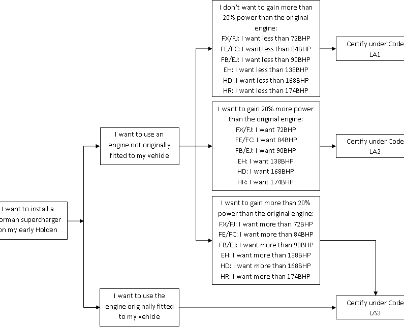
For this post, I will take a look at the registration hurdles we are likely to face in installing a Norman sueprcahrger to our early Holden. In an ideal world, supercharging our Holden grey motor would be as simple as bolt up and go. The bolt up part is tricky enough in itself. However, installing a supercharger is a modification which requires engineering certification. Supercharging has the capacity to substantially increase a vehicle’s power and performance and is generally considered on the same basis as a performance engine conversion (like installing a V8). In the information below, I will summarise the requirements from the National Code of Practice (NCOP) Supercharger and Turbocharger Installation Code LA3. Before anyone asks, I know full well that some engineers will pass a vehicle with substantially less than the below, and that some registration authority inspection stations will issue a roadworthy regardless of what is under the bonnet (“but my cuzzy has a blowa on his fooly sick Monaro mate, 1000hp, no engineers mate”) – I am only aiming to show what the guidelines are.
Our starting point is to determine exactly when certification for a supercharger is required. The table below gives some guidance. Essentially, if we are aiming for more than a 20% power increase (and we should be!), then certification will be required. Assuming that we are Norman supercharging our grey motor, then Code LA3 applies.

Image

Code LA3 specifies a number of requirements, listed below. Because FB/EK Holdens are pre-ADR, a number of mandatory safety upgrades are required. These are:
• Seatbelts must be installed for all seating positions (all outboard seating positions require retractor type lap/sash seatbelts and inboard seating positions either lap/sash or lap belts),
• Split or dual braking system. As the early Holden brake systems are single, this requires a new master cylinder and appropriate piping.
• Windscreen washers must be fitted. This could be a period type Trico set up, or an el-cheapo plastic bottle and pump from SuperCheap Auto.
• Two speed windscreen wipers with a fast speed of at least 45 cycles per minute and a slow speed of at least 20 cycles per minute must be fitted. Note that the original FB/EK single speed wipers are acceptable provided yours can be shown to have a cycle speed of 45 cycles per minute or more.
• A windscreen demister must be fitted. This could be a period Warmaride heater, an electric aftermarket heater or as simple as a 12V hair dryer plumbed into pool cleaner hose.
• A flat or convex external rear vision mirror complying with the latest version of ADR14 must be fitted to the driver’s side of the vehicle.
• Flashing direction indicator lights must be fitted at the front and rear of the vehicle (not a problem from EK onwards, though an option for earlier Holdens).
• The engineer signatory may specify a higher tyre speed rating than the original specifications and the fitting of an additional tyre placard indicating the minimum tyre requirements. The load rating of tyres must not be reduced from that specified by the vehicle manufacturer.
• A collapsible steering column must be fitted.

Additionally,
• Supercharger drive belts and pulleys must be shielded to prevent injury from accidental contact with rotating components.
• With respect to emissions, as our early Holden was manufactured prior to 1986, no emissions tests (as called up through ADR 37/00) apply. Similarly, because our early Holden was not certified to ADR83/00 (2005), a noise test is not required.
• Whilst the original Norman supercharger installations on early Holdens were contained under the bonnet, this may not be possible for all configurations. Any supercharger and induction system components sticking up above the original bonnet line must be covered with a bonnet scoop/bulge meeting the following:
a) the top surface of the scoop/bulge must not be more rigid than the original bonnet.
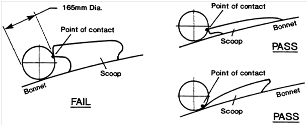
b) the scoop/bulge must be “low rise”. To check this, a 165mm diameter circle is placed on the bonnet in front of the scoop/bulge and rolled rearwards until it touches the scoop/bulge. The scoop/bulge must be low enough that no part of the scoop/bulge touches the circle above it’s centerline.

Image

c) Whilst there is no maximum height specified for a scoop/bulge, it must not restrict the field of view of the driver under normal operating conditions. The driver’s field of view requirements are determined by sitting in the driver’s seat with the seat pushed right back. It must be possible to see either the surface of the road eleven meters in front of the driver’s eye (red line in the diagram) or the front edge of the original body when looking across the top of the bonnet scoop (blue line in the diagram).

Image

There are some fancy ways of working out how tall the driver is, but a simple way is to take the eye position as a point 730mm above and 270mm forward of the junction of the seat cushion and squab. For our FB/EK Holden, this means we can (roughly!) fit a 6” tall bonnet scoop as per the photos below.

Image

d) The edges at the front of a scoop/bulge likely to contact a pedestrian in a collision must be well rounded with a minimum of 10mm radius. All edges and corners must have a radius of not less than 5mm.
e) The scoop/bulge must not have reflective surfaces that will cause glare.
f) Plastic or fiberglass is acceptable, providing that the hole in the bonnet does not substantially reduce the strength or impact resistance of the bonnet and no rigid component (such as an air cleaner or carburetor) protrudes beyond the original bonnet profile. This kind of defeats the purpose if we are installing the scoop to cover a Norman supercharger installation. In reality, it means either the scoop is made of mild steel of the same thickness as the original bonnet, or everything is tucked under the bonnet.
g) If any bonnet reinforcing braces are cut or modified, the bonnet must not be weakened and have no sharp edges.

Cheers,
Harv (deputy apprentice Norman supercharger fiddler).
327 Chev EK wagon, original EK ute for Number 1 Daughter, an FB sedan meth monster project and a BB/MD grey motored FED.
User avatar
Harv
Posts: 5043
Joined: Mon Oct 08, 2007 2:00 pm
State: NSW
Location: Sydney, Australia

Re: Harv's Norman supercharger thread

Post by Harv »

For this post, we will take a look at rotor clearance and end-thrust.

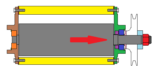
The rotor on a Norman supercharger is held in place by bearings at either end. The bearings are held in place to the end plates with circlips, preventing the bearing from moving axially. The means that when the bearings and end plates are installed, the casing, end plate and bearing are locked in position and cannot move relative to each other. In the overview image below, we can see:
a) The rotor (grey) lying in the casing (yellow),
b) The drive-end end plate (dark green) bolted to the right-hand end of the casing, with its bearing (dark blue) held in place by a circlip (pale green). Trapped between the end plate and bearing is the drive-end seal (purple).
c) The non-drive end end plate (brown) bolted to the left-hand end of the casing, with its bearing (orange) held in place by a circlip (pale green).

Image

The non-drive end bearing is often a two-piece bearing (like the Type 65’s bearing), where the inner and outer races are able to be pulled apart by hand. Whilst this sounds strange, the inner race has a wire cage that retains the bearing balls. The two-piece design means that the non-drive end bearing cannot take any thrust load at all – if the rotor shaft tries to move axially, the bearing simply slips out the inner race. This is useful in the Norman superchargers, as it allows the rotor steel to grow longer as it gets hot, expanding out through the rear bearing. If we assume that the rotor starts at ambient temperature (25ºC) and gets as hot as 75ºC, the 50ºC temperature change is likely to change the rotor length by around 0.06%. This means a Type 65 rotor will grow some 0.006”. Whilst this does not sound like much, bear in mind that typical cold end-clearance between the rotor and casing is 0.010-0.015” at the drive end and 0.025” at the non-drive end. As the rotor expands, it takes up quite a bit of the extra clearance at the non-drive end. The cold end-clearance between the rotor and casing at the non-drive end is determined by the thickness of the gaskets (shown in red in the attached diagram) between the end plates and casing (both drive end and non-drive end). The thicker the gaskets, the more clearance at the non-drive end.
The drive-end bearing is a one-piece bearing. Pressing up against the bearing is a thrust washer (shown in pink in the diagram above). The thrust washer is stepped so that it bears on the bearing inner race only. The thrust washer is keyed to the rotor shaft, though free to move along it. Pressing up against the thrust bearing is the drive pulley (shown in white), again keyed to the rotor shaft though free to move along it. Pressing up against the pulley is a pulley washer (shown in pale blue), followed by the shaft nut (shown in red). This is where things get interesting. When the drive-end assembly is put together and the shaft nut is tightened up, it begins to draw the rotor through the drive-end plate, bearing, pulley and washers (in the direction of the red arrow in the diagram). This reduces the cold end-clearance between the rotor and casing at the drive end. Thus for the drive-end, the cold end-clearance between the rotor and casing is determined by how far the drive nut is tightened. When assembling the supercharger, care must be taken not to “flog the hell” out of the shaft nut, as this will change the clearance. The shaft nut should only be adjusted with the end-plate off the casing so that the cold end-clearance between the rotor and casing at the drive end can be checked with feeler gauges. If the shaft nut is adjusted with the end casing on, it is not possible to determine what the resultant clearance will be. This also means that the nut must not move during operation (say by vibration).
It is thus important that the shaft nut be a lock-nut in good condition – not one that has been assembled/disassembled until the nylon is worn. An alternative to using nylock lock nuts is to use two jam nuts. This is prevalent in the later (Mike) Norman superchargers, where castellated jam nuts are used – see the image below, where one of the two castellated nuts has been removed whilst the other remains on the shaft.

Image

The process of having clearances set by the lock-nut occurs when the pulley washer is sized as per the image labelled 1 in the diagram below.

Image

Al – if you are reading this, be very wary of setting the drive-end clearance on your Judson. Talking to George, the Judson shaft nut does not “bottom out” i.e. it is as per the image 1 above. Tighten it too much, and clearances will change.

One way to limit the risk of shaft nut movement is to blueprint the pulley washer. This is done by allowing the shaft nut to bottom-out on its threads as per the image labeled 2. The shaft nut can then be torqued up tight, lowering the chance of movement. This then means that the cold end-clearance between the rotor and casing at the drive end is independent of how far the drive nut is tightened, and instead is determined by the thickness of the pulley washer. The pulley washer thickness is then chosen so that the cold end-clearance between the rotor and casing at the drive end is correct (around 0.010”). A thicker pulley washer will decrease the end-clearance, as per the image labeled 5. Note that if adding additional washers/shims to make a “thicker” pulley washer, care needs to be taken that the additional washers/shims do not bear against the shaft step, as shown by the orange shims in the image labeled 3. Shims/washers that bear on this step do not decrease the end-clearance... they just drive the shaft nut along the shaft. A thinner pulley washer will increase the end-clearance, as per the image labeled 4.
Overall, the process for setting the end clearances then becomes:
a) Install the bearing into the drive end plate.
b) Install the drive end plate/bearing assembly onto the rotor.
c) Install the thrust washer, drive pulley and pulley washer onto the rotor.
d) Tighten the shaft nut until it bottoms out.
e) Check the cold end-clearance between the rotor and casing at the drive end with a pair of feeler gauges, aiming for 0.010”. If the clearance greater than 0.010”, install a thinner pulley washer (or skim down the existing one). If the clearance is less than 0.010”, install a thicker pulley washer or shim washer.
f) Install the non-drive end bearing inner race onto the rotor.
g) Install the clearanced rotor and end-plate assembly to the casing together with an appropriate gasket.
h) Install the outer bearing into the non-drive end plate.
i) Fit plastigauge to the non-drive end of the rotor.
j) Install the non-drive end plate/bearing assembly onto the rotor/casing casing together with an appropriate gasket.
k) Remove the non-drive end plate/bearing assembly from the rotor/casing casing. Check the end-clearance by reading the plastigauge, aiming for 0.025”. If the clearance is less than 0.025”, replace the end-plate gaskets with thicker ones. If the clearance is more than 0.025”, replace the end-plate gaskets with thinner ones.

With respect to bearing thrust, there is not a huge amount of thrust loading in a Norman supercharger. The main culprit for thrust loading is (often minute) amounts of misalignment between the crankshaft and supercharger pulleys. The Norman supercharger (and it’s Judson cousin) relies on an interference fit on the rotor shaft to hold the rotor in place – there is no effective thrust bearing. If the rotor tries to move in the direction of the red arrow in the diagram, it can slip through the bearings. This reduces the end-clearance between the rotor and casing at the drive end and can cause end-plate gouging. This would be the case if the crankshaft pulley is too far forward (in front of the supercharger pulley). If the rotor tries to move opposite the direction of the red arrow in the diagram, the shaft nut, pulley washer, pulley and thrust washer will bear up against the drive end bearing inner race, preventing rotor movement. This would be the case if the crankshaft pulley is too far backwards (behind the supercharger pulley). Whilst not catastrophic, it is not great practice to load up a ball bearing in this fashion. Given the above limitations in thrust control, it is important that supercharger pulleys are adequately aligned. This is a particular issue when vee-belts are used, and less of an issue where non-shouldered gilmer belts are employed.

Cheers,
Harv (deputy apprentice Norman supercharger fiddler).
327 Chev EK wagon, original EK ute for Number 1 Daughter, an FB sedan meth monster project and a BB/MD grey motored FED.
User avatar
Harv
Posts: 5043
Joined: Mon Oct 08, 2007 2:00 pm
State: NSW
Location: Sydney, Australia

Re: Harv's Norman supercharger thread

Post by Harv »

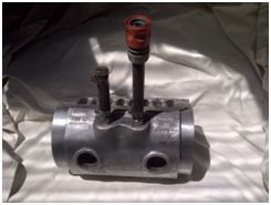
For this post, I am going to start to present some of the processes used in overhauling a Norman supercharger. The example I will use below is a Type 65.
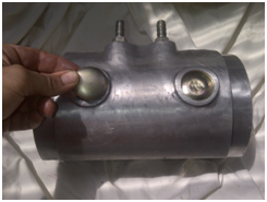
From previous posts, we had taken a look at the casing and had had it honed. Once the casing has been honed, care must be taken that the cast iron liner is not left to rust. A thin coat of light machine oil (Singer sewing machine oil from Woolworths) should be maintained at all times. The casing can be cleaned up and then polished on a buffing wheel. This can be as simple as a light cut and then polish, or could be a full sand down to remove dents and scratches followed by a multi-step polish to a mirror finish. In the example that follows I have used a light cut and polish, rather than the latter. This gives a nice shine and protects the aluminum sufficiently for our purposes.
Prior to any further assembly, the casing should be given a good clean with some kerosene, the water jackets flushed. I prefer to fit some temporary steel 3/8”NPT nipples to the water jackets and then some heater hose offcuts to let me connect to tap pressure. I then give the water jacket a really good flooosh out backwards and forwards to make sure it is clean. After the flush out, air-blow everything down and then reapply some light machine oil to the liner.
Image

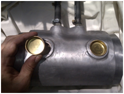
Fit some new 1½” brass welsh plugs to the water jackets. The original plugs were of the cup-type (albeit steel), which can be used. Used a smidgen of sealer around each plug and then tap the plugs in using a socket as a drift.
Image

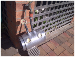
It is a good idea to pressure check the water jackets at this stage. The temporary steel 3/8”NPT nipples and heater hose can be used to connect to tap water pressure. For a pressure gauge, you can use a low-cost tyre pressure gauge from SuperCheap/Repco (as per the image below).
Image

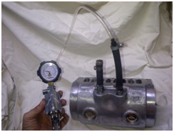
For those wanting a bit more accuracy (or where your tap pressure is not high enough) a hand pressure pump can also be used (the one in the photo below is a MityVac pressure/vacuum pump – handy for pressure testing, but also for vacuum testing things like Stromberg power bypass pistons and automatic transmission vacuum modulators).
Image

My tap pressure is around the 15-20psi mark, though yours may be lower. Bear in mind that a Holden grey motor will only generate 7psi radiator pressure (controlled by the radiator cap), whilst the later red/blue/black motors can generate up to 14psi… this is why I like to test to 15psi. When testing the casing water jackets, fill the casing with water and vent out any air from a high point before fitting the pressure gauge. Crack the water tap and bring the pressure up slowly, looking for any weeping. Shut the water off and make sure it holds pressure for a few minutes. WARNING: whilst it is unlikely that the casing will give way, there is a moderate potential that the welsh plugs are ejected at high speed. Do not stand in front of the welsh plugs! A face shield is not a bad idea.
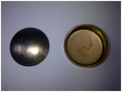
Of note, I’ve found that the 1½” brass cup-type welsh plugs (shown below on the right) do not seat very well on the Type 65 Normans (the alloy casing lands are quite shallow), and have a tendency to blow out at 15psi. I recommend instead that you fit 1½” cadmium plated steel dome-type plugs (shown below on the left).
Image
The dome-type plugs are tapped in with a ball-pein hammer and expand, holding them more securely than the cup type. Go easy on the tapping process – a few light taps are better than thumping the hell out of the casing.
Image

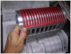
From most of the photos I have seen, the original Norman casings were either bare alloy (the earlier “Eldred” Normans like the Type 65) or purple anodized (the later “Mike” Normans). The early, early “Eldred” Normans did however have carnation-red end plates. Notwithstanding this, it remains common practice (and can look pretty cool) to paint in between the fins of the Type 65 Normans with red paint. If you are going to do this, now is a good time to do so. Clean the casing fin area up with some thinners or wax/grease remover and then mask up. A good engine enamel will suffice for this task, as normal paint will not usually handle the heat/fuel exposure. A good choice is Dupli-Colour Engine Enamel in &*#@ Red (DE1605), whilst the primer is Dupli-Colour Gray Engine Primer (DE1612), both available from SuperCheap Auto - typically one coat of primer, then three wet topcoats of red. In between wet coats (10 minute wait time as these are wet coats), wipe down the tops of the fins with a rag lightly covered in thinners. Once the paint had cured, do a final clean up of the tops of the fins with thinners.
Image

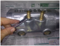
Once the casing is painted, fit the brass 3/8”NPT nipples to the water jackets. The nipples are handy as “handles” in some of the next few steps where the casing end plate bolts are torqued up.
Image

Note that NPT is a tapered thread which uses a metal-to-metal seal. There is no need to use Teflon tape or thread sealant on the threads unless they are badly damaged. Teflon tape and thread sealant are for straight (not tapered) thread… using them on tapered thread is the equivalent of using a pair of pliers to undo nuts. It’s not a bad idea to use a flare nut spanner on the nipples, as the brass is quite soft.
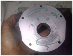
With the casing prepared, we can turn out focus onto the end-plates. Check the inside surfaces of both the drive end and non-drive end end-plates for gouges. It is quite common to find circular grooves either from the rotor shifting around and rubbing, or from something getting inside the casing (loose nut, bit of grit, busted vane spring etc). Grooves on the drive-end plate can also be caused by excessive rotor end thrust (say from misaligned pulleys). The grooves can act as a pathway for the compressed air/fuel mix, allowing leakage around the vanes and hence lower boost pressure.
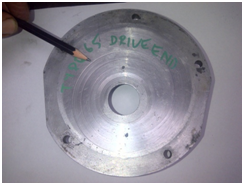
Image
Image

To remove the gouges, you can put the plates in a lathe and turn down the surface until they are flat. However, most home workshops (including mine ) don’t have access to a lathe. A simple solution is to lap the gouges out. This is a little more labour intensive, but very much cheaper than purchasing a lathe. A lapping plate is made by purchasing a thick (~½”) sheet of glass, a little bigger than a sheet of sandpaper (9”x11”). Glass plate of this size can often be got from your local glazier as an offcut – mine cost $5. A couple of stick-on rubber legs from Bunnings will stop the plate sliding around, whilst two bulldog clips will hold the sheet of paper in place.
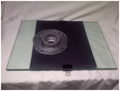
Image

To lap out the gouges, start with course wet-and-dry paper (80 or 120 grit), and apply a little water to float out the particles from the paper surface. The end plate is then held down with gentle hand pressure, and rubbed across the paper in a figure-eight motion. Do not go backwards or forwards or in circles as this can cause grooving in the plate. Care needs to be taken to keep the pressure on the plate fairly even (i.e. not leaning forwards onto one side). Once a uniform surface finish has been made (rubbing out the marks), change the paper to a finer grade. Wash the end plate in water to remove any old grit, then go again with the finer paper. By moving successively through the finer grades of paper, a nice clean surface is obtained. I stopped at 400 paper, as there is no need for a mirror finish on this surface – remember that the end plates have a moderate degree of porosity (see the image below).
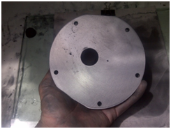
Image

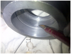
Once the end plates gouges are removed, check inside the bearing mounting surfaces for any small burrs in the aluminum where the bearing had grabbed, either in installation or disassembly. These marks are not a major concern provided they do not impede the bearing from being reseated, and can be removed gently with a sharp file.
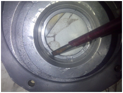
Image
Image

Finally, give the end plates a clean-up in some soapy water, rinse them off and air-blow dry. Protect the aluminum by giving the surface a quick cut and polish on the buffing wheel, again rinsing off afterwards.
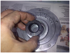
Time to put together out newly machined end plates. Starting with the drive-end end plate, lightly oil the inside of the bearing boss with some light machine oil. Tap in the new seal using a socket as a drift. Protect our nicely-flat end-plate face by doing this operation on a wooden surface padded out with some newspaper.
Image

Take care to make sure the seal is fully (though gently!) seated, and square to the bore. Once installed, smeared some more light machine oil around the lip of the seal, ready to take the rotor shaft.
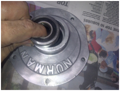
Fit the new drive-end bearing, either with a press or by using a socket as a drift. Note that either the press plate or the socket should rest on the bearing outer race only – not the inner race.
Image

Note that this is a shielded (sealed) bearing, so no greasing is required. Take care that the bearing is fully seated, and square to the bore.


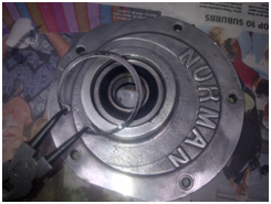
Lightly oil and then install the bearing snap ring, taking care that the snap ring is fully seated into the groove. This then completes the assembly of our drive-end end plate.
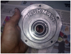
Image
Image

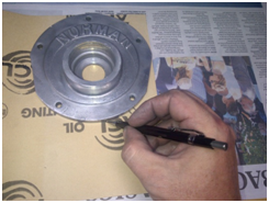
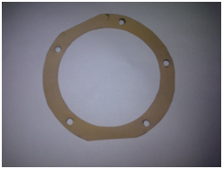
Use the assembled end-plate and casing to cut a drive end gasket.
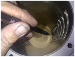
Image
Image
Image

As a starting point, I use ACL Gasket Material Pack 04 to suit Oil Jointing, which is 0.4mm thick (SuperCheap Auto part number 765164). Whichever gasket material you use, make sure you record the thickness as it is important to setting the rotor end-float later in the assembly process. I did a similar gasket cutting a little later for the non-drive end plate gasket.
Check the non-drive end plate for gouges or burrs, and lap/remove them as needs be. Polish, clean and dry the plate ready for assembly.
Assemble the non-drive end plate by again lightly oiling the bearing boss, and then pressed in the bearing outer race. Note that the non-drive end bearing is a two piece unit, so the inner race is added separately.
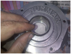
Image

Install the bearing snap ring, taking care that it was fully seated in its groove.
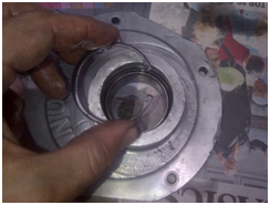
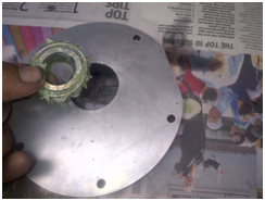
Image

Trial fit the inner bearing race into the end-plate.
Image

Note that the inner bearing race is free to move on the outer race, but an interference fit on the rotor shaft. This means that if you put the bearing into the end plate and try to push the rotor through, the rotor grabs the bearing inner race and separates the inner/outer races. The easier way is to install the bearing inner race onto the rotor, and then install the combined bearing inner race/rotor into the end plate. For the time being, store the inner race away.
Note that the non-drive end bearing is not a sealed unit, and requires grease packing. In this case, I have used Shell Gadus S3 T100. This grease:
a) is suitable for roller and ball bearings (pretty damn important given that is what it is going onto… some greases used for king pin and chassis greasing will not be suitable),
b) is good for 160ºC (a high temperature range is important particularly if no water injection is used when we first get the unit going),
c) can handle higher bearing speeds,
d) is water tolerant (important if we are using water injection upstream of the supercharger), and
e) has a long service life (important as Norman superchargers are not fitted with grease nipples).


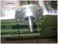
After getting the end plates ready, prepare the rotor by giving it a clean-off in some kerosene, and then lightly oil with light machine oil. The drive-end end plate is then slipped over the rotor, taking care to be gentle with the lip seal. Note that the photograph shows the gasket and bolts in place temporarily.
Image

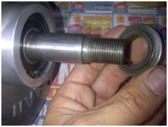
Assemble the thrust washer and key onto the rotor shaft, taking care with the orientation such that the stepped inner landing bears up against the drive end bearing inner race.
Image

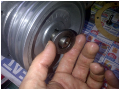
Install the drive pulley and pulley washer. Note that the pulley has again previously been given a light cut and polish on the buffing wheel, giving a nice shine, though not a mirror finish.
Image

We now need to set the cold end-clearance between the rotor and casing at the drive end. As we have seen previously, this can be done in one of two ways:
a) relying on the shaft nut to lock (nylock nut), or
b) allowing the shaft nut to bottom out, and choosing an appropriately thick pulley washer to set the clearance.
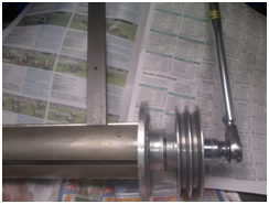
Personally, I prefer the latter. Whichever one you choose, we now need to install the shaft nut and tighten it. To tighten the assembly, I use a piece of steel flat bar (1’6”x1’¼”x6.5mm) wedged into the rotor slot to hold the rotor still whilst torquing up the locknut (this piece of flatbar is a handy Norman tool... I can see it getting a fair bit of use in the future ).

Image

This size nut could probably be torqued up to 150lb/ft when new. However, recognise that the thread on the rotor shaft is not in pristine condition, has a keyway cut through it, is not heavily loaded, and that if stripped would be a bugger of a repair. For this reason, I only torque the nut to 50 foot-pound. If you are choosing option “a” above (nut not bottomed out), then lightly tighten the nut.
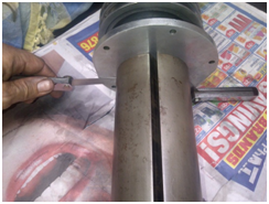
Once the assembly is torqued up, checked the clearance between the end plate and rotor using a pair of feeler gauges.

Image


We are aiming for a clearance of 0.010-0.015”, as used for Judson superchargers. Too little clearance and the rotor will bind/rub, too much clearance and the gas will not be pressurised. If using option “a”, adjust the shaft nut until you have the correct clearance. If using option “b”, select a thinner/thicker pulley washer to get the correct clearance - if the clearance it too big, install a thinner pulley washer (or skim down the existing one), and if the clearance is too small, install a thicker pulley washer or shim washer.


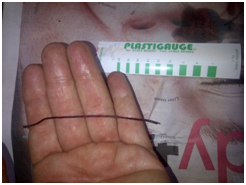
Now that the drive end clearance appears we can set the non-drive end clearance. The end-clearance is a lot harder to check on this one, as the rotor “floats” through the bearing. This means that you can’t assemble the unit and use feeler gauges like the drive end. Instead, a product called Plastigauge is used. Plastigauge is a little string/stick of material that looks similar to plasticine. It is of very accurate dimensions, with different grades of Plastigauge used to measure different clearances.
Image

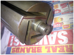
The Plastiguage is applied to the non-drive end of the rotor, as per the photograph below.
Image

We will then assemble the rotor, and “squish” the Plastigauge. As the Plastigauge is squished, it flattens out. The width of the squished Plastigauge then indicates the clearance. We then open up the casing again and read off the width of the squish using the little green indicator cards seen in the picture.
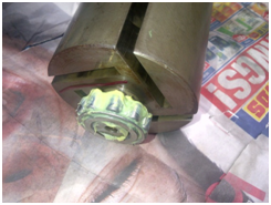
Fit the non-drive end bearing onto the rotor, taking care to either press or drive it on squarely.
Image

Assemble the rotor/drive end assembly into the casing, using the newly cut gasket. Tighten the end-plate bolts. For the Type 65 Norman, these are five ¼-28UNFx1” bolts, and should be torque to 50 inch-pounds (not foot-pounds!). This is not a very high torque, but bear in mind that the bolts are small, the threads lubricated and are into aluminum. The water jacket nipples are quite handy here to use as “handles” to stop the casing rotating whilst torqueing the bolts.
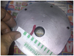
The non-drive end end plate and gasket is then gently installed, taking care not to bump the Plastigague. The respective end-plate bolts (five ¼-28UNFx1” for the Type 65 Norman) are again torqued up to 50 inch-pounds, taking care not to turn the rotor as this is done. The bolts are then undone, and the non-drive end plate is then removed (gently), and the Plastigauge examined. As the Plastigauge has been squished, it flattens out. The width of the squished Plastigauge then indicates the clearance, and is read off using the little green indicator cards. In the image below the thickness is around 0.2mm, or 0.008”. We are aiming for a clearance around 0.025” (as per Judson supercharger practice).
Image

If the clearance is too large, thinner gaskets (either or both of the drive end and non-drive ends) can be used. If the clearance is too small, thicker gaskets can be used. Remember as my starting point I used 0.40mm (0.016”) thick gasket paper for both the drive end and non-drive ends. This means we start with a total of 2 x 0.016” = 0.032” of gasket material to play with. We could change one gasket, or both gaskets if needs be to get the right thickness combination for our end float. Note that neither gasket will change the drive end clearance. Repco and SuperCheap sell gasket sheet only as thin as 0.4mm (as thick as 3.2mm), whilst CBC Bearings stock 0.3mm (0.012”). To get thinner sheet try Blackwoods, whose stock both 0.15mm (0.006”) and 0.25mm (0.010”) as part numbers 05118683 and 05334302 respectively.
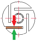
Once we have the right gaskets selected, the vanes can be put into the rotor and the casing end plates (finally) buttoned up. Care should be taken that the vane grooves are on the counter-clockwise side of the rotor (as viewed from the drive end). In the image to the right, the grooves go where the green arrow is, not the red arrow.
Image

As noted above, new Bakelite vanes can be sourced from Bearing Thermal Resources. When doing so, it is a good idea to specify the Bakelite as slightly oversized, and then machine it down to suit your specific rotor. Particularly, the width of the vane must be machined down such that it is only as wide as the rotor (remember that we only have about 10 thou of clearance either side to the casing). It can be quite difficult to file and then sand down these end surfaces to a fine finish, square and high tolerance. To assist, we can again use our lapping plate. The vane is held in a simple lapping jig, made from some aluminum angle iron (from Bunnings) and two bolts with wing nuts to clamp either side of the vane.
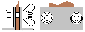
Image

The vane is placed in the jig on a flat surface so that it is square with the bottom of the angle iron. As the vane is lapped, both the vane and the angle iron will be machined down. This slows down the lapping process, which is not a bad idea given how easy it is to machine the Bakelite (very easy to sand off a little too much). Once one end is square and finished (lapped down to about 400 grit paper), the rotor is removed from the clamp and compared to the rotor. The opposite end of the vane is then clamped in and lapped down to the right overall length. Note that new Bakelite vanes should be soaked in engine oil overnight before installing (reused vanes just need a light coating of light machine oil).
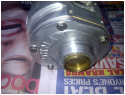
With the casing buttoned up we can then tap in the non-drive end welsh plug (for the Type 65 Norman this is a 17/8” brass cup-type plug), using a socket as a drift to drive it in squarely.
Image

The plug provides a pressure seal for the non-drive end of the supercharger. When we get around to pressure testing the entire casing/manifold, we will need to check that this plug remains nicely seated. This pressure testing will be done with air, and will be done when we set the manifold relief valve (pop-off safety valve).
The next item we will look at is the inlet manifold. The manifold for the Type 65 bolts to the top of the casing. Give the manifold a light cut and polish on the buffing wheel, and again clean it up in some soapy water before air blowing dry. Use the clean manifold to trace out the gasket required.
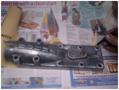
Image

Bear in mind that this is a large surface area, relative narrow and liable to be somewhat uneven… not a bad idea to use the thick 0.4mm gasket sheeting for this gasket to give plenty of take-up.
The studs for the Type 65 inlet manifold are six ¼”-28UNFx1¾”, and four 5/16”-18UNCx3” studs (present). If you need to get hold of new studs it can be quite difficult, especially the ¼”-28UNF size. An easy way is to use some high tensile bolts with the heads cut off then dressed.
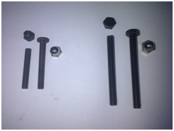
Image

These should be matched up to acorn nuts for the “period correct” look. You can of course use plain bolts (as many early Normans do), though studs and nuts are a lot neater. The acorn nuts are available in stainless from Lee Brothers Engineering in Parramatta if you can’t get them locally. Care needs to be taken when installing the studs if the “cut the head off a bolt” method is used. The casing holes are through to the water jacket (not blind), and hence it is possible to install the studs until they touch the cast iron liner. It is a good idea to install the studs so they are not touching the jacket, as the cast iron in contact with the high tensile steel will set up a galvanic cell, accelerating corrosion (it would be just my luck for the cast iron liner, not the stud, to corrode). Remember also that the acorn nuts only go “on” so far…. It’s a good idea to trial fit the studs first to check they are the right length. Once all looks good, install the studs with some Loctite blue thread locker. This is needed as the studs do not “bottom out” and lock if the “cut the head off a bolt” method is used. If engineers studs are used, they will bottom out, and Loctite is not needed (use thread sealer instead). Once set, the gasket and manifold can be mounted to the supercharger. The ¼”-28UNF studs can be torqued to 50 inch-pounds, whilst the 5/16”-18UNC can be done up to 80 inch-pounds. As you can see from the images to the right, it’s now looking more like a Norman.
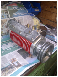
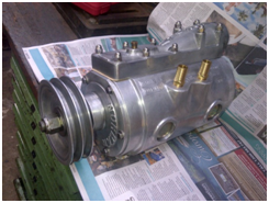
Image
Image

Cheers,
Harv (deputy apprentice supercharger fiddler).
327 Chev EK wagon, original EK ute for Number 1 Daughter, an FB sedan meth monster project and a BB/MD grey motored FED.
Blacky
Posts: 12229
Joined: Tue Jul 20, 2004 8:58 am
State: WA
Location: up in the Perth hills

Re: Harv's Norman supercharger thread

Post by Blacky »

Awesome detail Harv, this thread is a cracker :thumbsup: :thumbsup: :thumbsup: :thumbsup:
When you're faced with an unpleasant task that you really don't want to do, sometimes you just have to dig deep down inside and somehow find the patience to wait for someone else to do it for you.


Foundation member #61 of FB/EK Holden club of W.A.
User avatar
Harv
Posts: 5043
Joined: Mon Oct 08, 2007 2:00 pm
State: NSW
Location: Sydney, Australia

Re: Harv's Norman supercharger thread

Post by Harv »

Ladies and Gents,

A quick correction.

In an earlier post (early October 2013), I reported that “Weiand had found that for Rootes type superchargers, running 92 octane fuel, with no intercooling and with no ignition retard that pinging will not occur with an effective compression ratio lower than 12:1. 92 octane fuel seems a little low given that 98 is freely available in Australia.”

I had made a mistake however as petrol in Australia is sold by it’s Research Octane Number (RON), whilst American petrol (gasoline) is sold by the average of it’s RON and it’s Motor Octane Number (MON) i.e:
• Australian octane = RON
• American octane = (RON + MON)/2.

RON and MON are similar, being just two different ways to measure when a fuel will ping. The upshot of this is that American octane numbers (for the same fuel) seem lower. As a rough guide,
• Australian 95 octane = American 91 octane
• Australian 98 octane = American 93 octane.
If we then translate Weiand’s rule into Australian, they saw that for Rootes type superchargers, running 97 octane fuel, with no intercooling and with no ignition retard that pinging will not occur with an effective compression ratio lower than 12:1. That sounds more realistic.
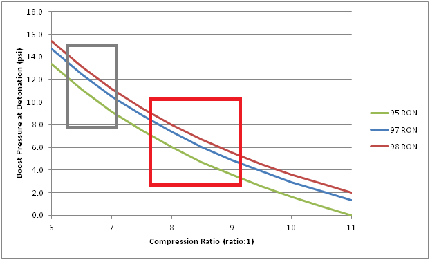
Note also that the chart I presented that brought together the Weiand and Miller/Bell/Bell’s experience was also incorrect, and was really in US octanes. Re-drawing the chart in Australian octanes:

Image

The grey box I have drawn on the graph indicates the range of compression ratios seen in factory Holden grey motors (6.5:1 to 7.25:1) whilst the red box indicates the same for EH-HR Holden red motors (7.7:1 to 9.2:1). The graph shows that for our grey motor running on 98 RON premium pump fuel we should be able to achieve 10-13psi of boost without pinging (and about 9-11psi if we run el-cheapo 95 octane). This is also more realistic.

Apologies for the error.

Cheers,
Harv (deputy apprentice Norman supercharger fiddler).
327 Chev EK wagon, original EK ute for Number 1 Daughter, an FB sedan meth monster project and a BB/MD grey motored FED.
parisian62
Posts: 3996
Joined: Wed May 11, 2005 2:19 pm
State: NSW
Location: Sydney
Contact:

Re: Harv's Norman supercharger thread

Post by parisian62 »

I am going to start to present some of the processes used in overhauling a Norman supercharger
Great work Andrew! :thumbsup: I'll order 2 while you're at it... :ebiggrin:
Feelin free in a '61 FB.
Member of FB-EK Holden Car Club Of NSW Inc.
Check out the Rebuild of Old Timer
User avatar
Harv
Posts: 5043
Joined: Mon Oct 08, 2007 2:00 pm
State: NSW
Location: Sydney, Australia

Re: Harv's Norman supercharger thread

Post by Harv »

Only 2? I got bloody carried away again and have ended up with four :oops: plus another two on loan.

Heres the deal - you bring me your Norman, and I'll provide the labour for free to overhaul it :mrgreen: .

Cheers,
Harv
327 Chev EK wagon, original EK ute for Number 1 Daughter, an FB sedan meth monster project and a BB/MD grey motored FED.
User avatar
Harv
Posts: 5043
Joined: Mon Oct 08, 2007 2:00 pm
State: NSW
Location: Sydney, Australia

Re: Harv's Norman supercharger thread

Post by Harv »

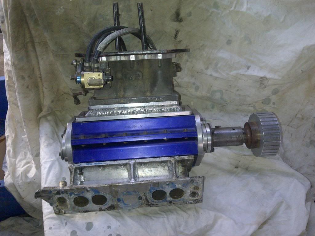
This is getting out of hand. I turn my back for 5 seconds, and another Norman finds it’s way into the house. This one is another of the later (Mike) Normans, 12” casing. Fitted to the top is a set of Hilborn injection.
Image
Hilborn injector is a model U-3, serial number 106. Three 2” throttle plates.

The injector was originally purchased from Hilborn in the US on the 25th of July 1972 by R Brown from Glenanga South Australia (probably a Rowley Park Speedway competitor... if anyone knows of Mr Brown, I’d love to hear from them – already chasing the historic speedway guys). The original fuel pump was a PG150A-0, similar to the one currently on the unit set up for counter clockwise rotation with methanol fuel. The original metering valve was a #54, as existing. The injector was installed on a Peugot 403 engine of 1550cc (70ci) using a F500A fuel filter with Size #8 fittings. A secondary bypass of Hilborn #5 (F510-5) using a bypass spring 0.016 diameter, flow .66, jet 115.

The unit was origanlly fitted to a Peugot 403 engine. This is a 1,468 cc (80mm bore and 73m stroke = 90ci) straight four with a crossflow hemi head. The engine produced 65 hp (48 kW) at about 5,000 rpm and 75 lb•ft (102 N•m) of torque at 2,500 rpm. To get 1550cc would mean going 90 thou over, which would be unusual (these are wet lined rather than bored so more likely to replace liner). Unlikely to be the 1618cc Peugot 404 engine (1960-75, 66-85bhp and 97 ft. lb. @ 2,500rpm) or 504 (1796cc) engine. If anyone knows Pug engines and wants to school me on how you get 1550cc from one, I’d love to hear it.

Plan is to put this one in the longer term project department, then build a Norman blown grey motor meth monster :mrgreen: . Slowly putting the bits together.

Cheers,
Harv (Dr Frankenstein, Norman meth monster department).
327 Chev EK wagon, original EK ute for Number 1 Daughter, an FB sedan meth monster project and a BB/MD grey motored FED.
User avatar
Harv
Posts: 5043
Joined: Mon Oct 08, 2007 2:00 pm
State: NSW
Location: Sydney, Australia

Re: Harv's Norman supercharger thread

Post by Harv »

Ladies and gents,

I’d like to back track a little to my recent posting on relief valves, and reflect a little bit on a discussion I have had recently with a gentlemen who owns a rather cool running Norman. This machine has had some damn clever engineering… the kind of stuff that makes you stop and think.
An option that has been used on this particular vehicle is to utilize a radiator cap to act as a relief valve. This is a clever way to build a simple relief valve, as different pressure rating caps (eg 7, 10, 13 or 15psi) can be used to adjust the relief pressure. Radiator caps are readily available up to 30psi. A weld-on radiator neck from the local radiator repair shop can readily be brazed into a supercharger manifold. However, some caution needs to be taken when using this approach:
Radiator caps have a large opening at the bottom, about the same size as the radiator filler neck. For most radiator caps, this hole is about the same size as the relief valve required. However, the radiator fluid (or in our case air/fuel mix) has to flow through the radiator inlet/outlet nipple, shown as the green arrow in the diagram below:

Image

The inlet/outlet nipple is much smaller than the radiator neck, acting as a restriction. There is a good chance that this restriction can be too small, leading to overpressure. It may be necessary to braze in multiple inlet/outlet nipples to get sufficient surface area.
Radiator caps are best known for keeping the pressure inside the radiator (or in our case the boost inside the inlet manifold). However, there are two types of radiator caps made – closed and recovery. If using a radiator cap for a relief valve, a closed cap must be used. Closed caps only open under pressure. A recovery radiator cap also acts as a vacuum breaker. The radiator cap not only has a pressure spring, but also a vacuum valve. When cold, both the pressure and vacuum valves of the cap remain closed. As the car warms up, the pressure in the cooling system rises. If the pressure begins to exceed the caps rated pressure, the pressure valve opens. As the engine load reduces, the pressure valve closes as the pressure comes down. As the vehicle cools down, any steam in the system will condense, and any hot air will shrink. This causes a vacuum in the radiator, and the vacuum valve opens. For older recovery radiator systems, air is drawn in through the vacuum valve to break the vacuum. For later cars with recovery coolant systems, coolant is drawn in from the overflow bottle. The vaccum required to open the vacuum valve will vary with manufacturer, though is very low. If we use a recovery-type radiator cap as a relief valve, the cap will again start out with both the pressure and vacuum valves of the cap closed. If we make too much boost pressure (or if we bang the blower), the pressure valve opens. However, under cruise conditions there is often a vacuum in the inlet manifold. The amount of vacuum will vary with different engines, but could be sufficient to allow the vacuum valve to open. If this occurs, the engine will draw in unfiltered air. The (potentially dirty) air will also bypass the carburetor, leading to a lean air/fuel mixture and the potential for pinging or engine damage.
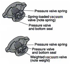
Additionally, there are two different types of recovery radiator cap produced (not to be confused with “closed” and “recovery” type caps). The first type is known as a "constant pressure" type cap, as shown in the top image below:

Image

With this design, the vacuum valve is held shut by a very light spring, creating a totally sealed system. If this type of radiator cap is used on our supercharger, boost pressure will starts to rise immediately because the closed vacuum valve prevents pressure from escaping. The second type of cap has an open variety of vacuum valve (often called “pressure vent” caps), as shown in the bottom image above. This type has no spring to hold the vacuum valve shut, only a small calibrated weight. The intention with this type of cap is that when the engine is first started (and under light operating conditions), pressure can vent through the vacuum valve. This allows the cooling system to operate at atmospheric pressure, reducing strain on the water pump seals, hoses, radiator, and heater core. As the engine starts to heat up, the escaping steam or coolant pushes the vacuum valve up and shut. This seals the radiator system tight, and pressure begins to build in the radiator. As the engine load reduces, the pressure in the radiator drops, and the valve opens again. If we use this type of valve, we will start out with the pressure valve open. The engine will start with vacuum in the inlet manifold, drawing in unfiltered air. The (potentially dirty) air will again bypass the carburetor, leading to a lean air/fuel mixture and the potential for pinging or engine damage. As the engine loads up, the inlet manifold will change from vacuum to boost pressure. An air/fuel mixture will flow out the radiator cap and into the engine bay. This will happen every time the vehicle comes on and off boost. Whilst it is tolerable to vent a “banged blower” into the engine bay every now and then, it is not a great idea to frequently vent an air/fuel mixture into the engine bay. For this reason, “pressure vent” style caps should not be used as relief valves.

Cheers,
Harv (deputy apprentice Norman supercharger fiddler).
327 Chev EK wagon, original EK ute for Number 1 Daughter, an FB sedan meth monster project and a BB/MD grey motored FED.
mmciau
Posts: 3
Joined: Mon Apr 07, 2014 7:55 pm
State: SA
Location: Marion, South Australia

Re: Harv's Norman supercharger thread

Post by mmciau »

Harv, I've joined the site to add to the vane blower story as I can remember.

Mike Mcinerney
User avatar
Harv
Posts: 5043
Joined: Mon Oct 08, 2007 2:00 pm
State: NSW
Location: Sydney, Australia

Re: Harv's Norman supercharger thread

Post by Harv »

Ladies and Gents,

Please extend a warm welcome to Mr McInerney :D .

As you guys have seen over the last few months, I have been trying to contact a number of people associated with Norman superchargers. There have been a few lumps and bumps along the way (the FED boys are proving hard to find :oops: ), but I've also had some real wins. I've managed to contact both Mike and Bill Norman 8) :ebiggrin: , and also Mike McInerney. Most of you can figure out where Mike and Bill fit into the picture, but I'm guessing not so many will be familiar with Mike McInerney. Time for the first of Harv's anecdotes :mrgreen: .

I like stories. And I especially like stories about old racing cars. In the coming months I am going to post some stories about old Norman supercharged racing cars. The stories are going to be diverse, and don’t be surprised to see them going off on a tangent... bear with me, as the best stories are the ones that paint a picture of the era. I will also try to link some of these stories together where I can. Bear in mind that these anecdotes are a work in progress, and I probably won't get it right the first time... like always, if I'm wrong, point the error out please.

Elfin, Bluebird and Norman – Australian Land Speed Records.

Elfin Sports Cars Pty Ltd is the oldest continuous Australian racing car manufacturing company, founded by Garrie Cooper and manufacturing sports and racing cars since 1957. The original factory was located at Edwardstown in suburban Adelaide and is currently located at Braeside, Melbourne. Elfin is currently owned by Tom Walkinshaw, who also owns Holden Special Vehicles. Elfins have won 29 championships and major Grand Prix titles, including two Australian Driver's Championships, five Australian Sports Car Championships, four Australian Tourist Trophies and three Formula &*#@ titles. World Formula One Champion James Hunt raced an Elfin, as did French Formula One driver, Didier Pironi. Elfin also took out the Singapore Grand Prix, twice won the Malaysian Grand Prix and also won the Australian Formula Two Championship in 1972 with Larry Perkins in an Elfin 600B.

Between 1961 and 1964 Elfin made twenty open-wheeled single-seater Formula Junior and Catalina vehicles. The two models differed only in minor specifications with the majority built as Formula Juniors. International Formula Junior class rule require production-based engines with a either 1000cc/360kg car or 1100cc/400kg car, using production gearbox cases and brakes. I understand that the Elfin Formula Juniors were originally fitted with Cosworth &*#@ Anglia (105E) 1100c engines, though the Catalinas were fitted with a larger 1475cc &*#@ engine to meet Australian class rules.

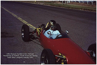
Elfin Catalina Chassis Number 6313 was built for Dunlop Tyres for use on the Lake Eyre salt to determine certain characteristics for the tyres that were fitted to Donald Campbell's Bluebird land speed record attempts during 1963. The Elfin was fitted with 'miniature Bluebird tyres" and driven over the salt to determine factors such as co-efficient of friction and adhesion using a Tapley meter. The Tapley Brake Test Meter is a scientific instrument of very high accuracy, still used today. It consists of a finely balanced pendulum free to respond to any changes in speed or angle, working through a quadrant gear train to rotate a needle round a dial. The vehicle is then driven along a level road at about 20 miles per hour, and the brakes fully applied. When the vehicle has stopped the brake efficiency reading can be taken from the figure shown by the recording needle on the inner brake scale, whilst stopping distance readings are taken from the outer scale figures.

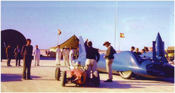
It is believed that the Elfin was running a (relatively) normal pushrod 1500cc Cortina engine with A3 cam and Weber DCOE carburettors for the Bluebird support runs. The photo below was taken on Lake Eyre and shows Donald Campbell alongside the red Elfin holding aloft a wind speed meter, with the 3,320kW Bluebird-Proteus CN7 to the right.

Image

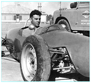
The photo below shows Ted Townsend, a Dunlop tyre fitter seconded to the Bluebird team in the Elfin.

Image

Bluebird went on to set the world land speed record at Lake Eyre at 403.10 mph (648.73 km/h) on July 17th 1964. Campbell has been quoted as saying “We've made it – we got the bastard at last”.


Some nice history, but I guess you are wondering where the Normans are, right? When the Bluebird record attempts were completed, the Bluebird Tyre designer Mr Andrew Mustard (of North Brighton, Adelaide) bought the Elfin from Dunlop. The Elfin was in quite poor condition as a result of its work on the Lake Eyre Salt, with the magnesium based suspension struts quite corroded. A restoration took place over the end of 1963 and into 1964, and a single Norman supercharger fitted (see, told you this story had Normans :mrgreen: ). The vehicle was then used at Mallala Race Circuit, and for record attempts for 1500cc vehicles in 1964 using the access road alongside the main hangars at Edinburgh Airfield (Weapons Research Establishment) at Salisbury, South Australia. The northern gates of the airfield were opened by the Australian Federal Police to give extra stopping time. At this time the Norman supercharged Elfin had:
• a single air-cooled Norman supercharger, driven by v-belts and developing around 14psi. The v-belts were short lived, burning out in around thirty seconds,
• four exhaust stubs, with the middle two siamesed,
• twin Amal carburettors,
• a heavily modified head by Alexander Rowe (a Speedway legend and co-founder of the Ramsay-Rowe Special midget) running around 5:1 compression and a solid copper head gasket/decompression plate. The head had been worked within an inch of it’s life, and shone like a mirror. The head gasket on the other hand was a weak spot, lasting only twenty seconds before failing. As runs had to be performed back-to-back within an hour, the team became very good at removing the head, annealing the copper gasket with an oxy torch and buttoning it all up again... inside thirty minutes.

The Norman supercharged Elfin, operated by Mustard and Michael McInerney set the following Australian national records from it’s Salisbury runs on October 11th, 1964:
• the flying start kilometre record (16.21s, 138mph),
• the flying start mile record (26.32s, 137mph), and
• the standing start mile record (34.03s, 106mph).

Ta da! Now you know where Mike McInerney fits into this. Say G'day to one of the few blokes to hold a Norman-supercharged Australian land speed record 8) .

The Australian national records are established (or broken) in conformity with the rules established by the Confederation of Australian Motorsport (CAMS). A national record is said to be a ‘class record’ if it is the best result obtained in one of the classes into which the types of cars eligible for the attempt are subdivided, or ‘absolute record’ if it is the best result, not taking the classes into account. The Norman supercharged Elfin falls into Category A Group I class 6. This class is based on the Fédération Internationale de l'Automobile (FIA) category system, and consists of automobiles (not necessarily production) with reciprocating two- or four-stroke supercharged engines of 1100-1500cc capacity, with free fuel. For the curious, our grey motored Norman blown early Holden is eligible for Category A Group I class 8 (2,000-3000cc).
In 1983 CAMS made a decision to fully align the Australian national land speed records with the FIA requirements. The pre-1983 records were not fully compliant with all the FIA requirements, and hence have been set in stone – they can no longer be challenged. This means the Mustard/McInerney records above are still standing. However, the decision meant that all available records were declared vacant and able to be filled under the newly adopted FIA requirements for a speed record attempt. Two of the Mustard/McInerney type records have since been set as follows:
• the flying start kilometre record (set by S Brooke in a Daihatsu Charade Turbo, 26.76s in 1985), and
• the flying start mile record (again set by S Brooke’s Daihatsu Charade Turbo, 40.03s in 1985).
The third Mustard/McInerney type record (for the standing start mile) does not have an Australian record holder. This is the case for many of the new (post 1983) classes, where no national records have been set (since 1983). Before you get too excited about going out and claiming all those records, there is a catch. A typical national record attempt is likely to cost between $5000 and $10,000... plus the vehicle costs.

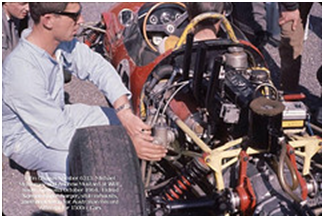
The photo below shows the Elfin in it’s 1964 guise at Salisbury, with McInerney in the foreground with his hands over the Amal carburettors.

Image

Directly below the four black exhaust stubs is what appears to be the red Norman supercharger, with an alloy end plate and brass welsh plug facing the camera. Note that in this state of tune the engine was able to be held together for only short periods (like nine minutes...) with only twenty seconds being typical with the car at full noise.

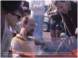
The photo below shows McInerney (in glasses to the left) with Mustard in the cockpit.

Image

This was not the Elfin’s only association with Norman superchargers. The Elfin was later modified to have:
• dual air-cooled Norman superchargers (identical to the single Norman used earlier), mounted over the gearbox. The superchargers were run in parallel, with a chain drive. The chain drive was driven by a sprocket on the crank, running up to a slave shaft that ran across to the back of the gearbox to drive the first supercharger, the down to drive the second. The boost pressure in this configuration had risen to 29psi,
• two 2" SU carburettors (with four fuel bowls) jetted for methanol by Peter Dodd (another Australian Speedway legend and owner of Auto Carburettor Services),
• a straight cut 1st gear in a VW gearbox. The clutch struggled to keep up with the torque being put out by the Norman blown Elfin, and was replaced with a 9” grinding disk, splined in the centre and fitted with brass buttons... it was either all in, or all out.

In the twin Norman supercharged guise the vehicle was driven by McInerney to pursue the standing ¼ mile, standing 400m and flying kilometre records in October 1965. Sadly, the twin-Norman supercharged Elfin no longer holds those records, as the ¼ mile and flying kilometre (together with a few more records) were set at this time by Alex Smith in a Valano Special. The Valano Special is a Valiant 225 slant-six powered car with a fibreglass Milano body made by JWF Fibreglass. The pictures below show Smith in the Valano at Templestowe Hill Climb (once Australia’s steepest paved road at a gradient of 1:2½ or 22º) in Victoria, a year later in 1966.

Image
Image

The day following the 1965 speed record trials (Labour Day October 1965), McInerney raced the twin-Norman supercharged Elfincar at Mallala as a "Formule Libre" as there was insufficient time to revert the engine back to Formula II specifications. The photo below shows the McInerney in the Elfin at Mallala Race Circuit:

Image

The car was used for training the South Australian Police Force driving instructors in advanced handling techniques, and regularly used at Mallala and other venues (closed meetings for the Austin 7 club, etc). It was sold by Mustard to Dean Rainsford of South Australia in 1966, though sadly without the Norman supercharger (by then it was running the mildly tuned Cortina engine again). The vehicle continued adding to it’s racing history, with Rainsford droving it to a win in the 1966 Australian 1½ Litre Championship Round 4 (the Victorian Trophy, Sandown, Victoria on the 16th of October 1966).

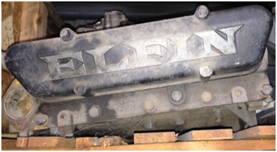
In the ensuing twentysix years it passed through nine more owners before Rainsford re-acquired it in 1993. After many years of fossicking, Rainsford has located the original Mustard/McInerney supercharged engine used in the 1965 record attempts. The engine is located in Gawler, South Australia (not far from the record track at Salisbury) ... sadly without it’s Norman supercharger – see photo below.

Image

As noted above, this anecdote is a work in progress. I'm still working on feedback from the Elfin Heritage Centre, and some other info coming on the Bluebird runs. As a tease, I'm lining up anecdotes on the Norman-blown Rowe/Wigzell speedcar, and some FEDs :mrgreen: .

Cheers,
Harv (deputy apprentice Norman supercharger anecdote collector).
327 Chev EK wagon, original EK ute for Number 1 Daughter, an FB sedan meth monster project and a BB/MD grey motored FED.
User avatar
Harv
Posts: 5043
Joined: Mon Oct 08, 2007 2:00 pm
State: NSW
Location: Sydney, Australia

Re: Harv's Norman supercharger thread

Post by Harv »

A couple of odds and ends for this post.

One thing that has been bugging me is that people refer to the “Type 65” as having a capacity of 65ci. No matter how hard I did the measurements and maths, I could not get 65ci/rev. In re-reading Eldred’s Supercharge!, I found the answer.
In earlier posts, I used a specific way to measuring supercharger capacity. The method I used (which is commonly used for modern superchargers) effectively says:
a) Measure how much air the supercharger breathes in when the first set of vanes swings past the inlet. This air will be pretty much at atmospheric pressure, and
b) Multiply that by the number of vanes.
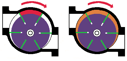
In the drawing below, this means work out the volume shown in red, and multiply it by six.

Image

This gives the volumes shown in the table below (note that I have added a few new superchargers to this table since my earlier posting):

Image

An alternate method was used by Eldred Norman (and is shown in Supercharge!):
“To ascertain the volume of the vane type, subtract the volume of the rotor treated as a solid form from the volume of the interior of the casing”.
This method says:
a) Measure how much air is in the supercharger at any given time, no matter how compressed it is.
In the drawing above, this means work out the volume shown in orange. Eldred’s method is neither more right nor more wrong than the modern method… just different. It also gives different results – a lot smaller number than the modern method. As an example, when we measure Gary’s Type 65 supercharger using the modern method, we get 118ci/rev. However, when we measure the Type 65 using Eldred’s method, we get 67ci/rev (near enough to 65ci, and hence the name).

Also from earlier posts, I showed how to set the non-drive end clearance by changing the gasket thicknesses. I noted that both Repco and SuperCheap sell gasket sheet only as thin as 0.4mm (as thick as 3.2mm), whilst CBC Bearings stock 0.3mm (0.012”). To get thinner sheet, I was going to try Blackwoods, whose catalogues show both 0.15mm (0.006”) and 0.25mm (0.010”) as part numbers 05118683 and 05334302 respectively. Unfortunately, Blackwoods don’t stock the sheet anywhere in the country . They could get it in for me... but only if I bought 100 metres worth(!). I did a fair bit of telephoning around, and got the same answer at most places – yes they stock it, but order it in specially at 100m a time. I finally found a supplier - Tucks Industrial Packings and Seals Pty Ltd (120 Ferrars Street South Melbourne, Vic 3205, telephone 0396902577, email sales@tucks.com.au, http://www.tucks.com.au). Nice blokes to deal with, and very helpful.
Cheers,
Harv (deputy apprentice Norman supercharger fiddler).
327 Chev EK wagon, original EK ute for Number 1 Daughter, an FB sedan meth monster project and a BB/MD grey motored FED.
User avatar
Harv
Posts: 5043
Joined: Mon Oct 08, 2007 2:00 pm
State: NSW
Location: Sydney, Australia

Re: Harv's Norman supercharger thread

Post by Harv »

Following on from my Norman supercharged landspeed record anecdote, the post below will share a similar story focussed on Speedway Normans. Norman superchargers were also used to some extent in Speedway racing in the 1960’s and 1970’s. This was particularly evident in South Australia, probably due to Eldred’s manufacturing operation being initially centred in Adelaide.

From our earlier Norman supercharged land speed anecdote, remember that Andrew Mustard’s Norman supercharged Elfin cylinder head work was done by Alex Rowe. Alex Rowe was a close associate of Eldred Norman. In the mid 1950’s to early 1960s Alex Rowe had a workshop 9 Eliza Street St Peters, Adelaide. Rowe did a variety of work from this location, including manufacturing and selling floor shifters for early Holden grey motor crashboxes. Part of the workshop was offered to Eldred Norman to manufacture superchargers (Eldred had his workshop in Halifax street). Rowe and his wife Helen later ran the Golden Fleece Service Station in about 1967/1968 at 87 Winston Ave, Melrose Park (now the current Winston Avenue Music Shop), and lived nearby at 130 Morgan Avenue. Eldred’s larrikin nature was well demonstrated one Friday night when he popped around to visit Rowe’s Eliza Street workshop in the early 1950’s... in his supercharged road racing 1936 Maserati Type 6 CM. The South Australian Police were looking for a race car seen coming up King William Street from the Halifax street region... funnily the car ‘vanished’ around Franklin Street!

Rowe began a long association with Norman superchargers by supercharging a £5 &*#@ Consul three-bearing crank engine in a midget in 1964. Midgets, also known as speedcars in Australia are methanol burning wingless Speedway (dirt track) vehicles. Modern midgets weigh in around 408kg with a 2721cc engine capacity (a little bigger at 3,000cc for standard engines, and a little smaller at 2,000cc supercharged) producing around 360bhp. Historic midgets were around 180-200bhp. Compare that to our trusty naturally-aspirated FB/EK Holden, coming in at 1100kg, with a 2300cc engine producing 75bhp... the historic midget’s that we will discuss below have a power to weight ratio seven times greater.
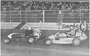
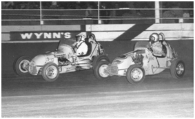
Rowe’s &*#@ Consul engine was probably the 1508cc 47bhp engine from the 1951-1956 MKI Consul (rather than the 1703cc, 59bhp 1956-1962 MKII Consul) as the Speedway capacity regulations were for around 2200cc unsupercharged and overhead valved, with 1600cc supercharged. The Norman-blown Consul motored vehicle was the first of the famous yellow SA#2 Speedway midgets, driven for Rowe by Bill Wigzell and is shown in the image below with Wigzell chasing Rex Sandy’s #56 midget in 1966 at the 392-yard Rowley Park Speedway, South Australia.

Image

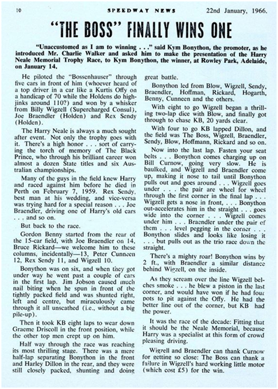
The article below describes one of Wigzell’s near-wins towards the end of the Consul-motor’s life in the vehicle.

Image

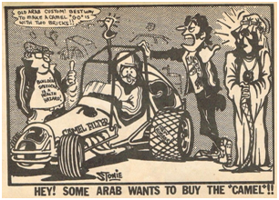
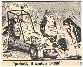
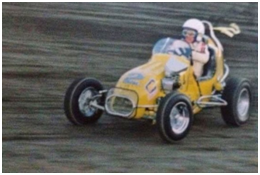
Rowe’s Norman supercharged &*#@ Consul motor was a real goer but unreliable, and for the 1966/67 season the Consul engine was replaced by a Norman supercharged Peugeot. The yellow SA#2 car (often referred to as the WonderCar) became a crowd hero by taking on and beating the best, including the Americans. After finishing third in the Rick Harvey Memorial behind Kym Bonython and Dean Hogarth, Wigzell won three of the four remaining big races that season - the Harry Neale Memorial, the fourty-lap South Australian State Round of the Craven Filter $6000 National Speedcar Drivers’ Championship and the Golden Fleece fifty-lap Derby. Wigzell won the State Round of the National Championship by more than half a lap despite driving with several slipped discs in his back, and in the fifty-lap Derby took sixteen seconds off the distance record and lapped all but four cars, which included the Americans Bob Tattersall (3rd) and Mike McGreevy (5th) in their Offenhausers.
The cartoons below, drawn by John “Stonie” Stoneham depicts the WonderCar, Wigzell and Rowe in the mid 1960’s.

Image
Image

The image below shows Wigzell driving the WonderCar with the supercharged Pug motor in 1966, whilst the image below that again shows Wigzell chasing Bob Tattersell’s McGee Racing Cams Tornado #13 &*#@ Falcon midget in the same year.

Image
Image

Wigzell continued to drive successfully for Rowe until the car was sold to another driver, Joe Braendler, part way through the 1969/1970 season.
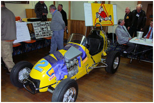
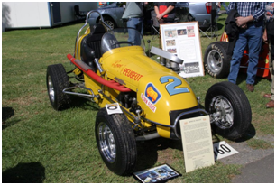
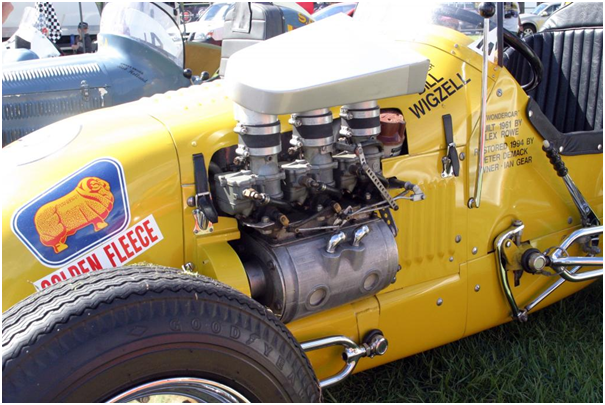
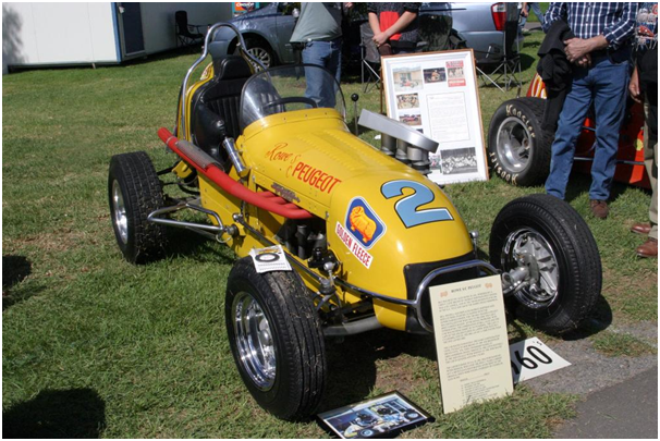
The WonderCar, in it’s restored 1966 Norman supercharged Peugeot guise, is shown below (I’m not sure where the top photo is, but the remainder are from the Adelaide Festival of Speed at Victoria Park Racecourse in April 2014).
Image
Image
Image
Image
Image
Image
Image

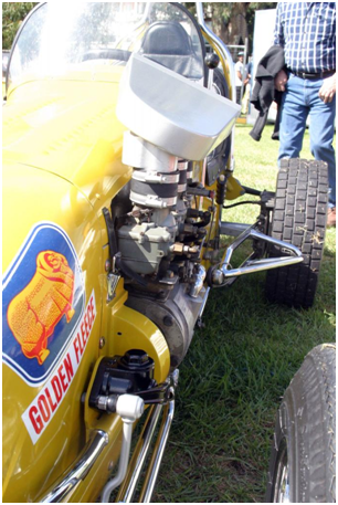
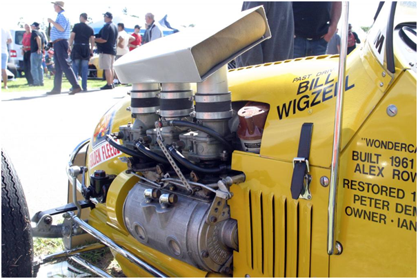
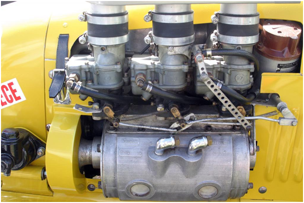
The WonderCar is currently running one of Eldred’s Type 70 superchargers. This is the same supercharger that is run in Peter Wooley's humpy Holden sedan, and Lindsay Wilson's EK Holden wagon. The supercharger can be identified from the model number distinctively cast into the side. Interestingly, the end-plate castings have both "Norman" and "Supercharger" cast into them. The earlier Type 65's have only "Norman" cast into the end plates, which are near-identical to the end plates used twenty years later when Mike Norman started making his extruded-casing machines. The WonderCar Type 70 is a water cooled (jacketed) supercharger, though it appears that the WonderCar runs the jackets dry and plugged off - when running on methanol, temperature increases due to compression and friction are much less an issue than if running petrol. The carburettors are triple Stromberg 97's with a progressive linkage - starting on the centre carburettor and then bringing in the two outer carburettors. This would give approximately 3 x 150 = 450cfm@3"Hg at wide open throttle. Assuming this is the ~1550cc Pug engine, Eldred's basic carburettor guidance would be two off 1¾" SUs (2 x 297 = 594cfm@3"Hg). This would suggest that the triple Strommies may be slightly under-carbed, depending on how much punch the motor is putting out. We will see later that this is a similar problem to that experienced on the Norman supercharged Stud Beasley Peugeot. Note however that the rearmost carburettor on the WonderCar has a linkage that climbs back over the top of the motor. I suspect it may be part of the “extra methanol” setup that Wigzell was reknowned for being able to operate from the cockpit to flood the engine with fuel at full noise.

The Rowe-Wigzell WonderCar speedcar was later driven by various drivers including Colin Hennig, Steve Stewart and was then later powered by a Mazda rotary engine driven by Steve Hennig at Speedway Park. The vehicle is currently owned by Ian Gear, shown below driving the vehicle (back to it’s Norman supercharged Peugeot engine) at the 490-yard Exhibition Grounds Speedway (the EKKA) in Brisbane, Queensland.

Image

Ian is shown below driving it at a historic meeting at the 390-yard Riverview Speedway, South Australia (also known as Murray Bridge Speedway, or currently the Murray Machining and Sheds Murray Bridge Speedway).

Image

Rowe later went on to build two Norman supercharged Renaults. I am not certain about the first Renault. I know that Greg Anderson drove a supercharged Renault for Rowe, built in 1972 and fitted to an Edmonds chassis, until the closure of Rowley Park in 1979. I’m not sure if this was the first or the second of the Renaults, nor if it was the same car that Anderson won the South Australian Speedcar Championship in the 1973/1974 season.
The second of the two Rowe Renaults was bought by Cec Eichler and was raced under the Kevin Fischer of Murray Bridge South Australia banner alongside the Suddenly #88 Supermodified sprintcar. The norman supercharged midget was also numbered #88 and painted in similar purple as the Suddenly #88 car – see image below. The midget was fitted with fuel injection and looked after by Fischer mechanic Ian Thiele.

Image


Rowe later went on to build a Norman supercharged Volkswagon (which was susceptible to spitting crank cases). Rowe was also the owner of a Norman-supercharged FB Holden, fitted with a floor shifter of his own manufacture.


Bill Wigzell was awarded the Medal of the Order of Australia (OAM) on the 11th of June 1979 for service to the sport of motor racing, whilst Alex Rowe was similarly made an OAM on the 26th of January 1987 for service to speedway racing. This honour is one that they share with the likes of Allan Grice, Craig Lowndes and Mark Skaife.

Another Norman supercharged speedcar was the Stud Beasley Peugeot (VIC#4), which was restored by John Waldock over seventeen years ago. The vehicle was originally built to run a V8 Buick engine, though was deemed by race officials to be overly powered. Stud then changed the motor out to a Peugeot 403 engine (1468cc) before campaigning it. To Stud’s frustration, when raced against the Rowe/Wigzell WonderCar the VIC#4 car came second place... despite the WonderCar running on three of it’s four cylinders. The difference was simple... the WonderCar was Norman blown. Stud made the logical choice, and fitted a Norman supercharger to the Pug motor. Over the years the vehicle went through a number of owners (including a stint as a hill-climb contender), and equally a number of engines – a Coventry Climax, an Alpha Romeo twin-cam, a 1618cc Peugeot 404 (fitted with the Norman supercharger from the Peugeot 403 engine), and also a stroked BMW engine.

Over time the condition of the car deteriorated, and was in a pretty sorry state when John purchased it. John was able to locate the original Peugeot 404 engine and Norman supercharger from Stud’s son Leroy Beasley. The supercharger was approximately 10” long and 4½” internal diameter, is air cooled and has 19 ribs/fins. Given it is purely air cooled and had a steel casing, it is likely to be one of the early Type 65 superchargers.

The supercharger was in very poor condition when John bought it. With little information available to work from, John drew on the memory of Eric Smith (who drove and maintained the car when it was owned by Stud Beasley), together with some photographs – see images below.

Image
Image
Image

Whilst there were some brackets mounting the supercharger casing, the casing itself was showing signs of corrosion of the hard-chrome liner coating. John had the liner dechromed and honed true to support good oil film retention (John was running castor oil in the fuel to aid in lubrication). The original Norman four-vane steel rotor had been replaced, with the replacement steel rotor incompletely machined at the time of John’s purchase. John made his own rotor from aluminium, drawing from his experience working on rotary vane compressors. John took the opportunity to radius the vane slot ends to remove the stress points incurred by square-edge milling. Interestingly, the end plates have been fitted with thin stainless steel sheeting inserts to prevent wear by the rotor ends. The end plates are fitted with a two piece roller bearing in the drive end, and a ball bearing in the non-drive end (this is the opposite of most Norman superchargers). The end plates and rotor nut were adjusted to achieve a 0.002-0.004” end clearance... considerably tighter than that employed on Judson superchargers (typically 0.010”-0.024”). The vehicle was missing the original manifolds, which John manufactured from the old photos. The inlet manifold runs a common plenum connected to three “fingers”, one for each carburettor. The fingers provided both a mounting point for the carburettors and also moves them outboard into the air flow. The vehicle runs three Stromberg 97 carburettors on a non-progressive linkage as per it’s original trim, though when racing the Beasley family added a fourth carburettor to try and cool the engine down by delivering more fuel (using the huge heat of evaporation of methanol). Like the SA#2 WonderCar, the VIC#4 car was probably marginally under-carburetted when running three Strombergs. The inlet manifold was fitted with a rubber-seated relief valve of approximately 1¾” diameter, set to 15psi. The vehicle typically ran at 8-9psi, though occasionally banged (hiccupped) through the relief valve.

The supercharger was originally fitted with a Gilmer belt drive. During Stud Beasley’s ownership it was noted that when the blower banged, it would snap the belt in short order. Stud rectified this by fitting a chain drive... chains don’t slip, but do transmit all that explosive (banging) force to the crankshaft. The thought of the chain (or worse) letting go certainly played on the mind of the driver at the time, Wayne Pearce. When John remade the vehicle, he reinstated the Gilmer drive belt system, together with a tensioner working from the outside of the belt (as per the original photos above). Initially, John experienced problems with the vanes chipping on one end. A motor mechanic friend who was involved in drag racing looked at it and commented that the belt was on the wrong side of the idler pulley and far too tight. This was causing the rotor to flex thus causing the vanes to chip. Bear in mind that John’s supercharger was running very tight tolerances on end float clearances, so any rotor flex has a substantive effect. After moving the idler to the inside of the belt (and running the belt somewhat looser), the vane chipping issue was resolved. Note that whilst vee-belts must be set very tight to avoid slippage, Gilmer belts are able to be run a lot looser due to their teeth meshing with the pulley teeth.

The photos below show the car being driven by John after being rebuilt.

Image
Image

The vehicle was later sold to Cyril Robinson, who then sold the vehicle to Peter Nunn. The pictures below are of Peter driving the vehicle.

Image
Image

Another Norman-blown midget was SA#75, which was originally built by Rex Hodgson. The Mitsubishi Sirius 4G62T engine was a 1795cc (80.6mm bore x 88mm stroke) single overhead cam eight-valve unit in relatively stock form, taken from a turbocharged Mitsubishi Cordia GSR (1983-89, 135hp in it’s factory turbocharged form). When owned by Hodgson the SA#75 car was running an 80ci/rev Magnusson supercharger and fuel injection unit. It is believed that the Magnusson supercharger and injection were purchased as a unit from the United States, implying that the Norman supercharger and Hilborn injection (that I now own) were fitted to the Cordia engine by a later owner. The Norman supercharger is one of Mike Norman’s 300mm units.

Image

Hodgson ran the Magnusson-blown Mitsubishi engine for only eight to ten meetings around 1985-87, as the supercharger had the tendency to melt drive belts. The car was then sold to Don Cave (from Highlander Crash Repairs in Holden Hill, South Australia), who jointly owned the unit with Colin Hennig. The car was driven by Steve Hennig and Ron Gates. Sadly, both Colin and Steve have passed away. I know that both the injection and the Norman were fitted to the car when Cave/Hennig owned it, and have spoken to both Gates and Bill Ahang, who worked on the Norman at the time. It’s possible that Hennig swapped the Norman and injection onto the Mitsubishi, as Gates remembers a snout being broken (probably the Magnusson’s snout, leading to it’s replacement with the Norman supercharger). The car was later purchased by Max Monk and subsequently parted out. Some parts were sold to Rob Gilbert, with the supercharger and injection going to the Wilsons at Tailem Bend before I bought it.

Another Norman supercharged speedcar was the SA#20 orange midget shown below.

Image
Image

This vehicle was built by Colin Cornelius and raced from 1972 until the closure of Rowley Park in 1979. The vehicle then sat idle until being purchased by Ian Gear in 1985, and remains in original unrestored condition. The vehicle has an all-aluminium 1565cc Renault 16TS engine (83bhp in naturally-aspirated trim), replete with the original hemispherical cross-flow head. The vehicle is fitted with a Type 70 Norman supercharger, being fed by two 1½” SU carburettors (~400cfm@3”Hg). This is slightly under Eldred’s recommendation of two 1¾” SUs (~600cfm@3”Hg), though is dependent on how heavily worked the Renault engine is. The SA#20 vehicle was successful, winning the Harry Neale Memorial when driven by Peter Maltby in 1971.
Some additional Norman supercharged speedway cars that I am aware, but have not been able to chase down include:


a) the Ron Ward as NSW#3 Peugeot speedcar. As far as I know, this was driven at one stage by Brian Mannion car, as shown below:

Image

b) Ken Tabe’s supercharged Peugeot, which was last seen in the Northern Territory.
c) Alf Kamilow’s supercharged Hillman Hunter,
d) Kevin Cook’s supercharged &*#@ Telstar. This vehicle was sold to Des James who drove it for one night at Speedway Park and wrote the car off.
e) Colin Kane’s supercharged Peugeot, and
f) Gary Dillon’s supercharged Volkswagen. I am not sure if this vehicle is related to the Volkswagon supercharged by Alex Rowe, nor if it is related to the Volkswagon that was supercharged by Eldred Norman around 1969 for speedway use in Brisbane (that vehicle had a habit of throwing sparkplugs into the crowd!)

Cheers,
Harv (deputy apprentice Norman supercharger fiddler).
327 Chev EK wagon, original EK ute for Number 1 Daughter, an FB sedan meth monster project and a BB/MD grey motored FED.
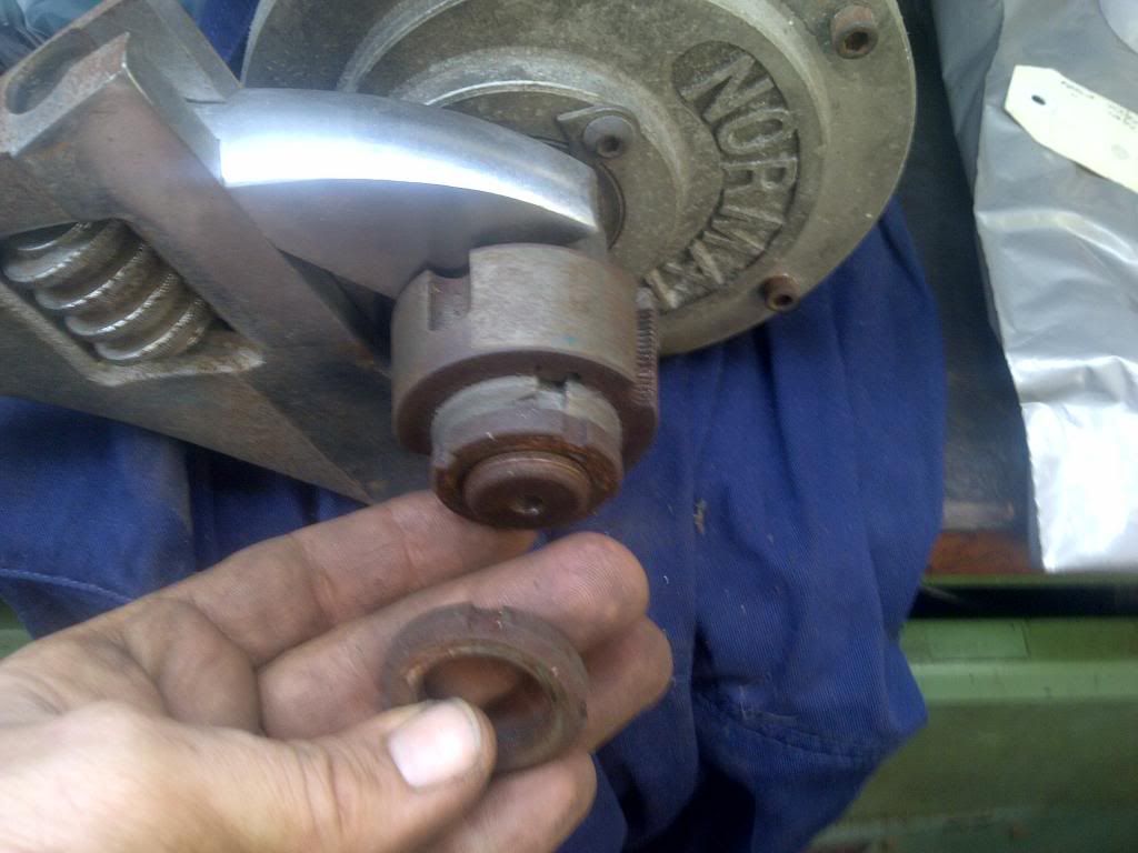
User avatar
Thommo
Posts: 3687
Joined: Mon Feb 05, 2007 4:42 pm
State: NOT ENTERED
Location: Adelaide

Re: Harv's Norman supercharger thread

Post by Thommo »

Harv wrote:The injector was originally purchased from Hilborn in the US on the 25th of July 1972 by R Brown from Glenanga South Australia (probably a Rowley Park Speedway competitor... if anyone knows of Mr Brown, I’d love to hear from them
There was a drag racer in SA named Rex Brown who used to have a zephyr 6 powered dragster, among other things, back in the day.
Image

Also, Welcome Mike :thumbsup:
Post Reply