Harv's Norman supercharger thread

Includes fuel system, cooling system and exhaust.

Moderators: reidy, Blacky

Post Reply
User avatar
Harv
Posts: 5062
Joined: Mon Oct 08, 2007 2:00 pm
State: NSW
Location: Sydney, Australia

Re: Harv's Norman supercharger thread

Post by Harv »

Ladies and gents,

Another newspaper clipping has surfaced (with thanks Kevin – appreciated) from Adelaide’s The News newspaper of September 28th 1964:

Image

Some interesting info here. The main photo shows Mustard’s twin-Norman supercharged Elfin, the subject of the Bluebird/Elfin landpseed trials anecdote I posted here a while back. The gentleman on the left of the photograph is Andrew Mustard, though I am not sure who the person on the right is (could be Eldred, though I have never seen him in eyeglasses before).

The article also shows Eldred busily working away on supercharger fitments for early Holdens, including the new EH. Note that the model indicates Eldred is making two versions, using the standard carb:
a) 7 ½ to 8 psi boost for acceleration, and
b) A 5½ psi boost for sustained high speed.
This is the period of time where Eldred was making the Type 65 and Type 70 superchargers (rather than the later Type 45/70/90’s).

Cheers,
Harv (deputy apprentice Norman supercharger fiddler).
327 Chev EK wagon, original EK ute for Number 1 Daughter, an FB sedan meth monster project and a BB/MD grey motored FED.
User avatar
Harv
Posts: 5062
Joined: Mon Oct 08, 2007 2:00 pm
State: NSW
Location: Sydney, Australia

Re: Harv's Norman supercharger thread

Post by Harv »

Ladies and gents,

In the post below, I am going to cover some of the things to work through in getting a manifold made up for your Norman supercharger, including Interpreting some of the guidance from Supercharge! and Supercharged! Design, Testing and Installation of Supercharger Systems. Before I launch into it, I’d like to thank Pete Mallaby, who made up the manifold I have been working on. Pete has taken my poor description and crappy details and made a truly beautiful piece of steel. Any issues with the manifold (like my bad measurement… as we’ll see) are my fault alone. For anyone wanting a good bit of steel (or ally) made up, I would highly recommend Pete’s work. Contact details for Pete’s business are:
Mallaby Sheetmetal
65 Piercefield Rd, Mt Thorley NSW 2330
PO Box 1, Broke NSW 2330
Telephone: (02) 65746300
Facsimile: (02) 65746311
Email: admin@mallaby.com.au
Image


The manifold should be kept as near to the cylinder head as possible. Longer distances makes top end performance suffer, although does not affect mid range torque. Some early grey motor Norman superchargers were mounted in place of the generator, as per the left hand image below.

Image

This made use of the standard GMH inlet manifold, and a length of rubber piping. Later grey motor Norman installations mounted the supercharger on a custom box manifold, as per the image in the middle. This positioning was also used by Mike Norman for Holden red motors. Red motor superchargers made by Eldred used the lineup shown to the right above, where the supercharger is mounted on the drivers side of the engine and a hose/piping used to go over the rocker cover to the standard inlet manifold. Whilst the left and right image line-ups give some flexibility in supercharger location, the middle image gives the shortest distance. It does however mount the supercharger very high, and can cause bonnet clearance issues.

For the middle option, the most satisfactory manifold (according to Eldred) is a box manifold feeding by short stub pipes direct into the inlet ports (the middle image above). Eldred recommended making the box of 3”x2”x 10-gauge tube (the modern equivalent to this is 50mmx75mmx4mm RHS). Bear in mind however that the early superchargers are very heavy… an alloy-case Type 65 with a 2” SU bolted to it weighs 20½kg! This means the box needs to be fairly substantive to prevent bowing.

The Norman supercharger is provided with a series of tapped holes in the casing, which are in the footprint of the supercharger mounting face. This makes it difficult to bolt to the box. One option is to run the bolts (studs) right through the box, as per the left hand image below.

Image

However, this option means that the bolts must be sealed to the box with washers and/or sealant, and will be prone to leakage (especially following a blower bang). Another option, as shown in the second image from the left, is to split the box to allow access inside. The box top half can then be bolted to the supercharger before the two halves of the box are bolted together. This process however gives a large flange joint in the box, which would be even more prone to leakage. It also places the nuts inside the box. Whilst the nuts can be locked or safety wired, it is not too comfortable a place to have them… a loose nut sucked through the engine is no laughing matter. An easier method is to top the box with a flange, as per the third image. This avoids leak-prone joints or piston-destroying nuts inside the box. Note that the Norman supercharger can be rotated and mounted sideways to increase bonnet clearance, as per the image to the right. Provided the carburetor-to-supercharger manifold still mounts the carburetor(s) in the correct orientation then no loss of performance results (the Norman does not know or care what way it is turned).

The third image above is perhaps the neatest solution, and is the same one as used by Eldred for his grey motor manifolds. A word from the wise – when specifying the width shown with a red arrow in the image to the below, make sure that you allow enough spave not only for the bolts to straddle the box, but also the bolts heads.

Image

Being foolish, when I had the manifold shown below made I forgot to allow for the bolt heads (and later felt like a right proper tool). Whilst allen-head capscrews only have small heads, even they take up space.

Image

The dimension shown by the red arrow above needs to be a touch under 2” for Type 65’s, and will vary with different superchargers. You’ll note in the image below that I had to make an alluminium sandwich plate to correct my mistake.

Image

The plenum (or box) part of the manifold serves two purposes. Firstly, it takes the discharge flow of the supercharger and distributes it to each of the cylinder head ports. Secondly, it acts as a pulsation dampener, smoothing out the flow (remember that our positive displacement Norman supercharger pushes out discrete “packets” of discharge every time a vane passes the outlet… the engine cylinder head valves equally cause pulses as each opens and closes). According to Eldred in Supercharge!, the manifold plenum volume should have a total capacity equal to about half the swept volume of the motor (for our 138ci Holden grey motor this would be 69ci or 1130mL). Corky Bell (Supercharged! Design, Testing and Installation of Supercharger Systems) is a bit more generous, indicating that the plenum should be at least as large as the swept volume (138ci or 2260mL). There is a balance here though in that the bigger the plenum, the more air/fuel mixture is present… and the bigger the explosion during a blower bang. The manifold I had made up has an internal volume of 106inch3 (120inch3 if you include the runners), or some 87% of the grey motor swept volume. This is a good balance between pulsation dampening and minimizing a blower bang.

It’s a good idea to weld some nipples onto the manifold to allow connection of boost gauges etc – one ¼”NPT and one 1/8”NPT nipple is a minimum.

Image


Whilst square-end pipe stubs welded to a section of RHS will work, the plenum to runner transition should be made as smooth as possible. Ideally, a bell shape can be made into each runner with the dimensions as shown in the image to the right.

Image


We will want to mount the relief valve on the manifold. The relief valve should be as large as practical and as close as possible to the supercharger outlet. Eldred recommends one at either end of the manifold. The box “lid” (or walls) will mount the relief valve, often achieved by drilling and tapping studs into the top of the box. The relief valve studs I will show below are ¼”-28 UNF thread. Good engineering practice is to engage the threads by 1½ times the bolt diameter, or in this case 3/8”. Making the box top 3/8” thick is a bit heavier than Eldred’s 5/32”, but it does mean that we can remove substantive amounts of steel (for more than one relief valve, or for tapping boost pressure gauges and water injection) without weakening the manifold. An alternative is to use a thinner lid, together with some nutserts, a thick mounting boss/compensating ring or to weld the relief valve studs on.

Of note, if you are making the supercharger manifold yourself you will have opportunity to weld/fit/fiddle/cut/weld/repeat to your hearts content. If you are having the manifold made by an outside shop (and your welding is as poor as mine), your ability to rework the manifold is limited. A key dimension that is painful to estimate is the exact location of the supercharger in space. A little too far forward or back and the pulleys will not line up. Whilst they can be shimmed, it is a lot easier if they don’t have to be (remember that driven pulley location on the Norman can sometimes affect drive end rotor clearance…painful to fiddle with). To solve this, it is recommended that the manifold top plate/lid/flange be made “closed” initially (at least if a workshop is making the manifold for you). The manifold is then bolted to the engine, and the supercharger sat in place. The supercharger can then be moved backwards and forwards until the drive and driven pulleys are aligned. Allignment can be checked by running a straight edge (steel rule, or a long spirit level) across the face of the pulleys. There is a pretty fair chance that the drive and driven pulleys are a little bit different (for example the belts spaced apart slightly differently). The best reference point to use (i.e. the point to see is “lined up”) is probably the midpoint between the two belts on both pulleys (rather than the pulley faces), as per the green arrow on the diagram below.

Image

This will require you to measure off the straight edge onto the pulley edge. The supercharger position is marked onto the manifold, and then the manifold removed. The hole for the supercharger to pass air/fuel into the manifold can then be cut out, and the mounting holes drilled. This gives excellent pulley alignment without having to shim the pulleys.

Image

Image

Another word from the wise. Mike Norman’s superchargers mount through rails cast into the supercharger, which are fitted with steel inserts. These are pretty square, as they are made by extrusion. Eldred’s superchargers however are individually drilled. Experience has shown that the holes are not all that square. One way to transfer the exact hole location to your new manifold is to use some transfer ink. To do this, clean both the manifold and the supercharger faces, then paint the supercharger face with engineer’s blue (for example Dykem 75182 Hi-spot Marker). This is a paste that is easy to spread, and does not dry out for months. It is used in industry (where two parts are to be mated together) to detect high spots on bearings, gears and other close fits. When the two parts are pressed together, the footprint of the supercharger should transfer to the manifold, showing exactly where the bolt holes are. The footprint can then be marked onto the manifold with a scribe and centrepunch. The engineer’s blue can then be cleaned up with some kero.

Image

Sadly, when I tried to do this it is evident that the Norman gasket face is nowhere near flat enough to transfer properly (it will need some good thick gaskets). After cleaning off all the engineers blue (I had blue fingers for days), I had to manually measure out each bolt hole from a reference point, estimating centres. If an engineering shop is making the manifold for you, they may well need the actual supercharger to work from.

Finally, bear in mind that the manifold and supercharger is going to be quite heavy, putting a considerable load on the cylinder head to inlet/exhaust manifold bolts. To prevent sagging over time (and hence leaks), some bracing is required. I made up some support braces to run from the manifold to the cylinder head bolts, using some 20x5mm flatbar.

Image

Whilst two braces are probably adequate, in theory you can mount many more on the cylinder head bolts. The braces (one flat, one S-shaped) simply bolt up to the supercharger manifold at one end and fit under the cylinder head bolts on the other. Of note though is that when the 5mm thickness of brace is put under the cylinder head bolt, the bolt only bearly engages some thread before tightening (if you try to tighten the cylinder head bolt back up to 65ft/lb, the bolt slips due to too few threads engaged. This is because the GMH cylinder head bolts have a very short thread length (which is why I ran out of thread). The idea behind this is that you only cut enough thread to do the job – any unengaged thread acts as a localised stress riser, leading to fatigue failure of the cylinder head gasket joint. As an aside, the GMH bolts are also reduced in diameter (they should be 7/16” diameter, but are less than that) to ensure that all the remaining threads are fully engaged. This reduces the bending stiffness of the bolt, increasing fatigue strength. To solve the short bolt problem, remember that GMH made both “long” cylinder head bolts (part number 7401119), and “short” ones (part number 7401120) for the grey motor. The bolts on the supercharger side of the cylinder head (passengers side) are the short ones (7401120), and are 7/16”-14UNCx3½”. I didn’t measure a longer bolt (from the drivers side of the cylinder head), but from memory the longer bolts are ½” longer (7/16”-14UNCx4”). The simple solution is thus to find a spare “long” bolt and use it.

With the manifold all prettied up, it’s time to think a bit harder about our relief valve. I’ve used the aluminium plate type valve favoured by Eldred, which consists of two aluminum plates (one circular, one triangular). Dimensions for the plates are shown below.

Image

Note that at the dimensions shown, the three ¼”UNF mounting bolts/studs do not quite clear the circular disc – either make three small notches in the disc, or increase the 2.4” measurement above slightly to space the bolts further out.

A hole is cut into the top of the manifold using a holesaw to allow the gas to pass out through the relief valve. From earlier postings, we need a minimum of a 2¼” diameter hole for red motors, and no less than a 1 9/16” (a little over 1½") hole for grey motors. These dimensions will give a sealing face (a ring shape) of 5/32” and ½” thick respectively. The hole I cut in the manifold above is 1.73” (a poofteenth bigger than the 1.68” internal width of the box section, and hence as big as can be done with that manifold). Note that the valve need not be mounted on the top of the box section – it will work equally well on the side (though avoid the bottom of the box as it will tend to accumulate any dirt, oil or condensing fuel, making the valve unreliable). I used some rubber sheeting under the circular plate to act as a gasket. You could also use normal paper gasket, but bear in mind that what comes out the valve is flaming, ignited fuel/air at a great rate of knots. Paper may not survive, and a leaking relief valve will sideline you in the Woolies carpark.

I also drilled three holes for the relief valve mounting bolts, and tapped them to suit ¼”-28UNF. I’ve used bolts here. The position of the relief valve bolts (how far they are screwed into the manifold) determines the spring compression, and hence the pressure setting of the valve. The more they are screwed in, the higher the valve set pressure. The only down-side of using bolts is that the bolt holes go all the way through the manifold (i.e. they are not blind). This means that gas can pass from the manifold up the threads, causing a leak. The bolts will need to be sealed (with thread sealer, just like some water jacket bolts on cylinder heads) when they are finally tested and set. It is probably neater to use studs, with nuts on the top to adjust. The studs can then be permanently sealed into the manifold. As a note, the bolts (or studs) used should be high-tensile, as they are under a pretty fair load constantly – mild steel may stretch over time.

The relief valve uses a (used) Holden grey motor valve spring to provide pressure. These have a spring tension of some 85lb/inch (i.e. if you compress the spring ½”, it exerts 42.5lb of force, if you compress it 1” it exerts 85lb of force). At 1” of compression we are very close to coil bind, meaning the maximum force we can exert with this spring (by compressing it 1”) is 85lb i.e. we can adjust the spring to deliver from 0 to 85lb of force on our aluminium disc. For the hole I cut (1.73” diameter), we have a cross sectional area of some 2.2inch2. By acting over the 2.2inch2 of manifold hole, the manifold pressure would need to rise to approximately (85lb ÷ 2.2inch2 =) 39psi before the spring is overcome and the valve lifts (at maximum spring compression). All up, it means we have an adjustable relief valve that can deliver from 0psi to 39psi. Cut the hole a little bigger, and you can handle a little less pressure. Use a stiffer spring, and you can handle more pressure. From previous posts, we set the valve at 150% of the targeted boost pressure. If we target 10psi boost (realistic for a Norman), we set the valve to 15psi.

With the valve assembled, it is now time to undertake the pressure test. The intent of the pressure test is to check that relief valve pops at the right pressure… too low and we will leak fuel/air, and too high and the manifold may rupture. The idea here is to test at multiple spring compressions. Having done that, for a given spring we will know that say 0.5” of compression gives you say 3psi setting, 0.8” compression gives you 8psi etc. That way you will not need to pressure test the manifold again if you pull the valve apart, just adjust it to the right compression distance. I made some blanking plates out of galvanized plate for the three runners, and out of vinyl-coated chipboard for the supercharger hole. I have glued some rubber sheeting to the plates with contact adhesive to serve as gaskets during pressure testing.

Image

The blanking plates for the runners were held in position with clamps, whilst I used the supercharger mounting holes to clamp on the chipboard blank. You will need to plug off any spare tappings in the manifold with steel or brass plugs. To measure the pressure, I used the same boost gauge I intend to use in the vehicle. When pressure testing, it is important to check each time that the valve is adjusted square. I measured between the top and bottom plates (see photo), and adjusted the bolts to square up the valve.

Image

The “zero” setting (i.e. the valve only just seated, with bugger-all spring tension) is a measurement of 1.94”. I used some soapy water around the relief valve to detect the onset of leakage, and the air compressor (gently!) to bring the manifold up to pressure. Be wary here that if you are heavy handed, or the manifold is weak it can go bang and throw steel at high speed for a long distance - good idea to clear the shed and wear a faceshield for this one.

Once you have finished the testing (and confirmed tha the vavle pops at the right setting), the valve must be locked. There is a risk that the bolts either vibrate loose over time (leading to leakage from the valve), or are accidently tightened right up in the future (leading to the valve not opening when it needs to). To prevent this, I have cross-drilled the bolt heads and fitted safety wire (I love drilling 1mm holes through high-tensile steel bolt heads on an angle). Safety wire works by connecting the bolts together in pairs. If one bolt tries to vibrate loose, the wire pulls on its partner. The wire is installed in such a way that the bolt being pulled on tries to tighten up. This provides resistance, and stops the first bolt from loosening. The wire also acts as a reminder that the nuts should not be played with (and hence inadvertently tightened).

Image
Image

You could always use locknuts, Loctite or jam nuts… I think lockwire looks cooler though. Those forum members with an aviation background are cordially invited to stop laughing at the quality of my lockwiring… at least it’s better than my welding .

I know that this seems to be a lot of stuffing around for the relief valve. Bear in mind that we are protecting the car (and anyone around it) from an uncontrolled explosion. Blower bangs are pretty common in race vehicles, though hi-powered dragsters are normally fitted with blower restraints (webbing) to hold the bits together during a bang. Our old Normans normally don’t use blower restraints. Anyone who is still not convinced that a supercharger bang is a major event should watch this video: https://www.youtube.com/watch?v=Ll3EvNMBgLA.

Cheers,
Harv (deputy apprentice Norman supercharger fiddler).
327 Chev EK wagon, original EK ute for Number 1 Daughter, an FB sedan meth monster project and a BB/MD grey motored FED.
User avatar
Harv
Posts: 5062
Joined: Mon Oct 08, 2007 2:00 pm
State: NSW
Location: Sydney, Australia

Re: Harv's Norman supercharger thread

Post by Harv »

Ooops... looks like the video link has moved - try this one:
http://www.youtube.com/watch?v=YeKwatZti1A

Cheers,
Harv
327 Chev EK wagon, original EK ute for Number 1 Daughter, an FB sedan meth monster project and a BB/MD grey motored FED.
User avatar
Harv
Posts: 5062
Joined: Mon Oct 08, 2007 2:00 pm
State: NSW
Location: Sydney, Australia

Re: Harv's Norman supercharger thread

Post by Harv »

Ladies and gents,

In the post below, I am going to cover the way that the ignition system can be changed to reduce knocking (pinging) in our supercharged grey motor. By retarding the timing, the engine will have less tendency to knock.

Our standard Holden grey motor has three separate components to ignition timing:
a) Advance which is added by rotating the distributor then bolting it down. This is often referred to as “flywheel advance”, and is constant regardless of what the engine is doing. For a grey motor, this is typically 2º.
b) Mechanical advance (sometimes called centrifugal advance). This is accomplished inside the distributor by a combination of spinning weights and springs, and varies with engine speed. It works by rotating the top of the distributor shaft clockwise to open the points earlier. For a grey motor, the following is a typical mechanical advance curve:

Image

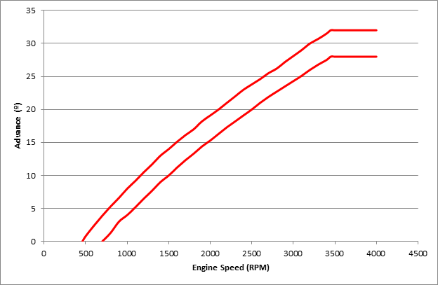
Note that there is a range of advance for a given engine speed (between the two red lines), as not all distributors are quite the same. The faster the engine spins, the more the distributor advances the timing (up to 28-32º at 3450rpm). The mechanical advance component can thus be described as “28-32º all-out at 3450rpm”.
c) Vacuum advance. This is again accomplished inside the distributor, but is driven by the vacuum module sitting on the side of the dizzy. The module is connected to the inlet manifold – the more vacuum in the inlet manifold, the more the vacuum module advances the timing. It works by rotating the breaker plate (and the points attached to them) anti-clockwise to open the points earlier. For a grey motor, the following is a typical vacuum advance curve:

Image


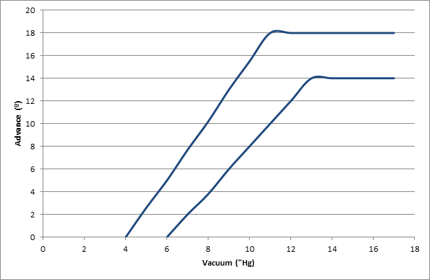
Note that there is again range of advance for a given vacuum (between the two blue lines), as not all distributors are quite the same. The higher the engine vacuum, the more the distributor advances the timing (up to 14-18º at 10-12”Hg of vacuum).

The total timing advance we get is thus a combination of flywheel advance (how far the dizzy body is turned), mechanical advance (how far the dizzy shaft top is turned) and vacuum advance (how far the points are turned), and depends on both engine speed (rpm) and load (vacuum). This needs thinking through in light of supercharged operation.

So just how much advance do we need for our Norman-blown grey, and how do we set it up?

Our first option (Option 1) is to rely on flywheel and mechanical advance alone, and set them up so that they do not offer too much advance as boost increases. From Supercharge!, we can see the following advice:
a) For every degree of “effective compression ratio” increase, retard the timing by 3º (for example, an engine on 9:1 might require 40º advance at peak r.p.m., whilst the same engine on 12:1 would only require about 32º). “Effective compression ratio” is a calculated number which tries to blend together an engines normal compression ratio with the “squeeze” obtained by supercharging. Effective compression ratio can be calculated as:
Effective compression ratio = √((Boost+14.7)/14.7) x static compression ratio
For example, a vehicle running 5 psi boost with a static compression ratio of 8.8:1 gives:

Effective compression ratio = √((5+14.7)/14.7) x 8.8 = 10.2
Note that Weiand use a different formula:
Effective compression ratio = (Boost/14.7+1)x static compression ratio
This gives a different result to Eldred’s method (for example, our 5 psi/8.8:1 vehicle would return an effective compression ratio of 11.8). The difference in calculation is something to be mindful of (for example if the effective compression ratio table in the Weiand Supercharger Installation Instructions Part A are used).
b) Undertake the timing reduction by reducing centrifugal advance, not by reducing flywheel advance (i.e. by regraphing the distributor, not by rotating the distributor).
c) Retard the distributor itself approximately 4º in addition to allow for decreased octane.

An additional set of advice is given by Weiand:
“We have achieved our best results with 12 to 20° of initial lead with a total lead of 32 to 36°. The advance should be in by 2,000 to 2,500 rpm... We have found that for all of the engines that we have dyno-tested, that the best power is obtained with 32° of total spark advance, with the entire advance coming in by 2,800 rpm. This is the maximum power with 108-octane race gasoline. You will probably not be able to use this much advance with pump gasoline. Our tests have shown that dropping the total spark advance back to 25° results in a loss of only two percent of power and torque up to 4,000 rpm and four percent of power and torque at 5,500 rpm. For this small loss in power, there will be a considerable reduction in detonation.” - Weiand Supercharger Installation Instructions Part A.
Weiand’s advice is consistant with guidance from other sources, for example:
“For most applications, the distributor should have a centrifugal advance mechanism set up so that the entire advance is in by 2,500 rpm. Typically, 34 degrees should be a safe level of ignition lead to provide close to optimum performance.” – Chevy High Performance Magazine

We can cross-check the Weiand guidance against Eldred’s views. If we take a grey motor running 7.25:1 static compression and add 10psi of boost to it, Eldred calculates
Effective compression ratio = √((10+14.7)/14.7) x 7.25 = 9.4
This is an increase of (9.4 - 7.25 = ) 2.1 degrees of compression, to which Eldred would recommend (2.1 x 3 = ) 6½ degrees of centrifugal advance timing reduction, plus up to 4º of static advance reduction. Our factory grey motor running flat-out has 32º of centrifugal advance, which we would reduce to 25½º. We also have 2º at the flywheel which would be reduced by around 4º, giving a total of 23½º total advance. This is pretty close to the guidance given by Weiand (around 25º total advance). As an interesting aside, early VW’s typically started with timing of 10º flywheel advance, and around 26º of vacuum advance (no mechanical) to give 36º total. This was tuned for the Judson supercharger by reducing flywheel advance by 5-7½º to give 28½-31º. This is again similar to Weiand’s advice.

So as a practical guide for setting up supercharged timing for a grey motor under Option 1, the following is a starting point:
a) Disconnect the vacuum advance and plug off the inlet manifold connection.
b) Regraph the distributor to give the following centrifugal advance, all-in at 2500rpm:
Image
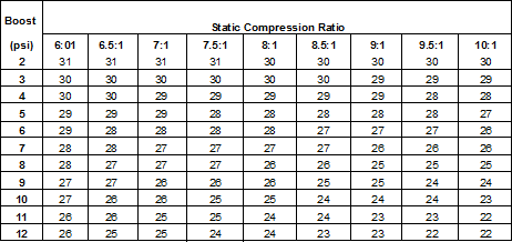
If you are unsure as to your compression ratio (say because the head has been worked) or boost level, then aim for 25º centrifugal advance, all-in at 2500rpm,
c) Set flywheel advance at 2º, and reduce/advance as necessary (probably 1-4º) to reduce knocking.

Option 1 is thus dependant on a particular engines boost/compression, but in summary uses no vacuum advance, changes mechanical advance from “28-32º all-out at 3450rpm” to (roughly) “25º all-out at 2500rpm” and tunes using the flywheel advance.

Our second option (Option 2) is to try to get full advantage of the mechanical advance, yet reduce timing as boost increases. We could do this with an electronic boost retard box, though this is not too period-correct. One way to do this is to utilise boost retard in a manner similar to vaccum advance (i.e. by rotating the breaker plate inside the distributor - kinda like vacuum advance in reverse). This is not as simple as just connecting up the factory Holden grey motor vacuum advance unit to boost pressure due to the internal configuration of the unit. As can be seen from the diagram below of the factory unit, vacuum acting on the green diaphragm causes a compression spring to compress, pulling on the rod to advance timing. Adding boost to the factory grey motor unit tries to make the spring stretch, bottoming out the unit.

Image

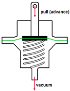
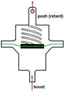
What we are looking for instead is a setup similar to that shown below.

Image

As an aside, this type of boost retard should not be confused with vacuum retard where timing is retarded with increasing vacuum, not boost. Vacuum retard is an evil process used as an emissions control device (lowering NOX emissions by dropping combustion temperature) in vehicles like the 1971-1976 Triumph TR6 and 1969-74 Jaguar Series ll and XJ6. As an example of a vehicle that did use the type of boost retard we are looking for, Chevrolet released the Corvair Spyder from 1962 with a 150hp turbocharged option. This vehicle did not use vacuum advance, but instead used a similar type of diaphragm module to measure boost. As boost increased, timing was decreased. Timing for the Corvair Spyder was as follows:
a) Flywheel: 24º
b) Centrifugal: 10-14º all in at 4500rpm
c) Boost retard: 7.5-10.5º per psi, all in at 1.5-2.5psi.
Thus a Corvair Spyder motor operating at 4500rpm and 2.5psi boost would have ignition timing of 24+10-11 = 21-23º. This is pretty close to the guidance given above by both Weiand and Eldred.

In Supercharge!, Eldred mentions this type of boost retard unit, indicating:
“It is difficult to get the correct spring tension and amount of travel correctly balanced with the boost pressure. However for those interested in trying this a total movement of the plate mounting the points, in the region of six degrees of the distributor will cope with an eight pound supercharge. The distributor itself will have to be advanced about eight degrees over the normal setting to compensate for the total loss of what was formerly the vacuum advance mechanism.”

In summary, Option 2 uses factory mechanical advance, reduces timing with increasing boost, and tunes with flywheel advance. Without using a boost retard box, Option 2 is not an easy one to pursue.

Option 3 is a simplistic version of Option 1, and is used by many race vehicles. This involves locking the distributor. Locking the distributor means that both the vacuum advance and flywheel advance are disabled, and all timing is done by changing the flywheel advance. The advance/static compression ratios shown for Option 1 can be used (or the simplistic 25º advance used as a starting point). Locking the distributor makes it’s operation more simple (and hence more reliable), though means that all the advance the car needs comes on at very low rpm and is fixed. This is OK for a car that runs flat-out all the time (like speedway or drag cars), but not so good for cars that operate over a wide range of speeds and loads (like your typical road car). At low rpm, a fixed-timing road car can perform quite poorly. Another drama of fixed timing is that it gives waaaaaay too much advance at startup compared to a “normal” engine. When cranking over the engine, the engine may fire the charge early (especially if the engine is hot), making the piston push backwards. This can break teeth from the starter or ring gear. One way around this is to install an ignition isolation switch inside the cabin, in parallel to the factory Holden key-switch. Turn the ignition isolation switch to off (ignition off, no spark) until the motor is cranking over strongly (2-3 seconds) then flip the ignition system back on.

In summary Option 3 is simple and reliable (lock the advance at roughly 25º)… just not well suited to anything that runs other than flat-out the whole time.

Whilst the above deals with mechanical and flywheel advance, we also need to think about vacuum advance. Opinions vary greatly as to the need for it in supercharged vehicles. For example:
a) Moss and Judson both recommend using vacuum advance with their superchargers,
b) Holley (Procharger) provides for a vacuum advance connection in their supercharger manifolds,
c) Several of the MSD Ignition boost retard units allow for programmable vacuum advance, and
d) Shorrock disconnected vacuum advance with their superchargers.

Generally, the supercharged engine will still develop vacuum (not boost) under cruise conditions, and vacuum advance can be useful for throttle response and fuel economy. Our first option for vacuum advance is to simply disconnect the vacuum advance and block off any connection on the inlet manifold. This is simple and cheap, though does sacrifice some throttle response and fuel economy.
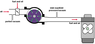
Alternatively, we can look at There are two positions we can take our pressure/vacuum signal from:
a) Ported vacuum – this is taken upstream of the carburettor(s) butterfly and will always be vacuum (never pressure), or
b) Inlet manifold – this is taken between the supercharger and the cylinder head, and will vary from vacuum to pressure depending on engine load.

Image

The two different locations will vary in pressure/vacuum as follows:

Image

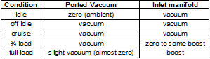
Note that this will vary slightly with configuration – for example if the carburettor is too small, then vacuum will be higher (lower pressure) at the inlet manifold but lower (closer to zero) at the ported vacuum connection.

If the standard ported vacuum connection location is used to set the timing, the distributor will still see vacuum under off-idle and cruise conditions (and advance the timing) – no harm there. However, as engine load (and hence boost) begins to increase, the distributor will continue to see vacuum, increasing timing (by up to 18º for a standard grey motor vacuum unit and distributor!). Advancing the timing with increased boost will cause substantive knocking.

Vacuum advance can be plumbed into the inlet manifold. In this location, the unit will see vacuum under off-idle and cruise conditions (and advance the timing). As engine load (and hence boost) begins to increase, the distributor will see boost (an absence of vacuum) and will reduce the (vacuum) timing advance to nil. The problem in doing this though is that at idle the distributor sees vacuum and retards timing. This can give a significant bog when you first put your foot down.

Whether or not we choose to use vacuum advance, we may wish to check the mechanical advance curve. Without putting the distributor on a regraphing machine, you can check the mechanical advance curve by marking the flywheel. The normal process for setting ignition timing utilizes a timing light. The light is connected to cylinder #1, and the engine allowed to idle at 480-520rpm. At this speed, a typical Holden grey motor should have zero (at most 1º) mechanical advance. Early Holdens were designed to run timed spark vacuum (the vacuum port connection is at the throttle body above the throttle plate), giving no/little signal to the vacuum advance module at idle (and hence no vacuum advance). Thus at idle we are really only checking the flywheel advance. For our Holden grey motor, when the timing light flashes it is aimed at the timing ball on the flywheel. The ball is located at 2º flywheel advance (note that the flywheel also has a “UC” mark a little anti-clockwise, which marks Top Dead Centre, or 0º advance). So our timing light is really checking that we have 2º of flywheel advance in our standard grey motor. The grey motor flywheel ring gear has 113 teeth (roughly 1/3 of a tooth per degree). Thus if we flash the timing light at more than 3450rpm, the dizzy should have advanced the timing 28-32º, or 9-10 teeth clockwise. To check the advance, put a series of coloured dots (with paint) under the flywheel teeth e.g.
0º mechanical advance = factory steel ball.
5º mechanical advance = red paint dot = 1.5 teeth to the right (clockwise) of the factory steel ball.
10º mechanical advance = blue paint dot = 3 teeth to the right of the factory steel ball.
15º mechanical advance = white paint dot = 5 teeth to the right of the factory steel ball.
20º mechanical advance = green paint dot = 6 teeth to the right of the factory steel ball.
25º mechanical advance = yellow paint dot = 8 teeth to the right of the factory steel ball.
30º mechanical advance = purple paint dot = 9 teeth to the right of the factory steel ball.
You can then run the car up to a given rpm, flash the timing light and see how much advance you’ve got by looking at what coloured dot is illuminated.

At some stage I’ll come back to ignition timing and post more – I currently know how to simply limit vacuum advance, but want to play around a bit more with mechanical advance in the standard GMH dizzy. The aim is to give a simple, no welding, backyard way to setup the dizzy for a supercharger. Watch this space.

Cheers,
Harv (deputy apprentice Norman supercharger fiddler).
327 Chev EK wagon, original EK ute for Number 1 Daughter, an FB sedan meth monster project and a BB/MD grey motored FED.
User avatar
Harv
Posts: 5062
Joined: Mon Oct 08, 2007 2:00 pm
State: NSW
Location: Sydney, Australia

Re: Harv's Norman supercharger thread

Post by Harv »

Ladies and gents,

In this post I will add some of the fiddly bits and pieces I have learnt in the last month in finishing up the Type 65 Norman rebuild.

Some time back I took a good look at drive pulleys and posted the results here. My original intention was to use a GMH red motor twin pulley as a drive pulley. These will bolt to the aftermarket grey motor harmonic balancer using the three “remover/puller” holes. I bought two GMH pulleys, bolted one of them up OK, pulled it off, cleaned and painted it… must have handled the two pulleys a dozen times. I need my eyes checked. Would you believe it, the GMH pulleys are two different groove sizes. For example, one groove is 5.25” diameter, the other 5.10” (the other pulley I have is 5.23” and 5.09”). Doesn’t sound like much (and hard to see by eye unless you are looking for it). However, for our use as Norman supercharger twin-pulley drives they are not suitable. Connecting two different drive pulley groove diameters to the driven pulley (same groove diameter) puts the pulleys into bad conflict. One belt would slip badly. For example, on the 5.25”/5.10” pulley, at idle the belt would slip 8” every second, and at full noise 80”. Way too much. I guess GMH only ever drove two different accessories (e.g. airconditioning and power steering) and never ran them as a twin belt.

To solve the drama, I have bolted up an alluminium twin pulley from a Chev (eBay special). It took some machining to fit, but at least is now the same pulley diameter (trust me… I measured it repeatedly). The bad thing about using Chev pulleys though is that the internal bore is much larger than the grey motor crankshaft (the Chev is 1.1” versus the 1” grey motor crank). This means it can be quite hard to centralise the Chev pulley onto the grey motor crank. I tried using one of the harmonic balancers as a template, and even taking quite some care could not get the three holes drilled perfectly concentrically. If using the Chev pulley it is recommended to either get a hub centric ring made up (a washer 1” ID and 1.1” OD), or to have the three mounting holes professionally drilled by a machine shop (3/8-24UNF on a 213/16” (71.44mm) PCD). Note when buying a Chev pulley that you will typically want one that lies very close to the harmonic balancer (rather than the “long water pump” type that stick out further). A Speedmaster PCE239.1008 item is not a bad choice (http://store.speedmaster79.com/).

The Chev drive pulley is 5.457” diameter, giving this particular Norman a drive ratio of 1.23:1. A fair amount of overdrive, though suitable for the Type 65. With a 6,000rpm practical redline on the Norman, this will impose a redline of no more than 4800rpm on the engine.

With the drive pulley sorted, I turned my attention back to the idler. From my previous posts, we identified that the Kilkenny Castings KC160 was a suitable candidate to run on the back side of a double vee-belt setup. These are intended as replacement idler pulleys for VN-VP Commodores. The bearings on the KC160 are a weird unit – 40mm OD and 17mm ID. The 17mm internal diameter is painful, as it is nigh-on impossible to buy an M17 bolt to act as a pulley spindle. One option that is useful is to replace the bearing with a 40mm OD/19.05mm ID bearing (bearing part number 6203-¾). These are an oddball bearing, with a metric OD and ¾” imperial ID. This would allow you to use a ¾” high-tensile bolt as the pulley spindle. In this case, it was easier to machine the existing spindle down to ¾” (and no… I couldn’t machine down to 17mm and use the existing bearing as the spindle threads clashed). Many thanks to Cooper for helping with the machining on this one – very much appreciated.

With the idler pulley sorted, I shimmed out the pulley spindle with some washers to align the pulleys and then chose belts. I ended up using two 11A1385 belts. This is the longest belt that the setup can handle, with the tensioner almost making the back of the belts touch.

Image

Whilst you could readily run smaller belts on this setup (for example 11A1375 or shorter), I maximised belt length to maximise belt wrap. This setup has 230º of wrap on the driven pulley, 155º on the drive pulley and 80º on the idler. These are pretty damn good values, with no need to tighten the absolute crap out of the belts to prevent slippage.

The belt tensioner on this Norman has been described in earlier posts, and works by clamping on to the supercharger drive-end snout. There is potential for this clamp to slip over time, allowing the belts to lose tension. To address this, I bought a small stainless steel turnbuckle from Bunnings, which bolted to the existing idler arm (see the earlier post which shows some drilled and tapped holes on the drawing). With a little persuasion, the other end of the turnbuckle now fits to the thermostat housing bolt.

Image
Image
Image

This is a very neat way to put tension on the idler, and stop it vibrating loose over time. It also means you can tighten the belts easily without trying to hold tension on the idler pulley with a long bar.

With the idler sorted, the grey motor fan became an issue. I needed to space the fan out some 1⅓” to clear the idler pulley (this gave 5mm clearance between the idler pulley and fan blade tip). A 2” thick Speco fan spacer will do the trick (part number 501707), cut down to 1⅓” thick. Be wary that the standard grey motor water pump shaft protrudes through the pulley, so the back of the cut-down spacer will need a 1” diameter hole drilled in it to suit. The standard grey motor fan bolts onto the water pump pulley with four short ¼”-28x½” UNF bolts, with some longer ¼”-28 UNFx2” bolts from SuperCheap needed.

Image

One drama here is that there is only 1” clearance between the fan and radiator in a standard FB/EK Holden - you may need to move the standard radiator forward to suit. An alternative is to run an electric fan, though this doesn’t feel too period correct.
I ran some new 5/16” steel fuel line to feed the SU. As the SU has a barbed inlet fitting this needs a short length of rubber hose to join. The steel fuel line thus needs a bead rolled into the end of it to prevent the rubber hose blowing off. A simple tool to do the job is sold by Aeroflow (part number AF98-2019).
Image
Image

One trick here is to utilise the existing grey motor fuel line by joining it with a brass coupler (½”-20 UNF threads and a 45º double flare seat either end to suit the original 5/15" GMH fuel line). Couplers like this are available from NBS Brake Supplies (http://www.nbsbrakesupplies.com.au/). This is handy also for anyone wanting to plumb twins or triples.

Image

And here a photo of the near-finished Norman:
Image

For this particular unit, my story ends here. I was pretty keen to fire it up, though the exhaust manifold I had would not allow the supercharger to fully sit square on the cylinder head. It would need some meat ground off the supercharger-to-cylinder head manifold to sit flat. As my exhaust was different to the one that will eventually go on the engine, I didn’t want to randomly grind some metal off the manifold. Even with a good sized gap in the inlet, this thing wanted to fire… the three seconds of running Norman that I got was sweet, sweet music. The Norman has now been packed up and sent back to it’s rightful owner. With a bit of luck, we’ll post some more here when it gets fired up in anger 8) .

Next Norman project will be to overhaul one of Mike Norman's units. Similar to the Type 65 above, but some subtleties. Following that, it's probably time to tackle my clutched Type 70 (the same type as Eldred was running on his HD ute). Watch this space.

Cheers,
Harv
327 Chev EK wagon, original EK ute for Number 1 Daughter, an FB sedan meth monster project and a BB/MD grey motored FED.
User avatar
Harv
Posts: 5062
Joined: Mon Oct 08, 2007 2:00 pm
State: NSW
Location: Sydney, Australia

Re: Harv's Norman supercharger thread

Post by Harv »

A short note here on gilmer drive belts. As per the discussion above, a gilmer drive belt on a Norman supercharger is not ideal, but equally is not uncommon on the later (Mike) Norman superchargers. The gilmer belts allow for zero slippage, and can break belts (or crankshafts or supercharger rotors) during a blower bang. Assuming that your new Norman has come with a gilmer drive pulley (and perhaps a belt), the question becomes what type of belt to put on the system (or what type of pulley to buy to suit the other one). The name “gilmer” is used somewhat loosely to describe a wide variety of belt profiles. The belt manufacturing industry refers to these belts as “timing belts”, as they allow positive synchronization between two pulleys. The one thing these belts have in common is that they have teeth, which in turn mesh with teeth on the drive/driven pulleys. However, some caution needs to be taken before rolling into your local Repco store and asking for a gilmer belt.

The first difference in gilmer belts is the belt profile. Gilmer belt drives are typically either trapezoidal, curvilinear, or parabolic profile. The trapezoidal profile, available since the 1940’s, is the easiest to identify. The trapezoidal pulleys and belts have flat peaks and roots, with sharp corners. The curvilinear and parabolic belts are harder to pick, as they come in a variety of configurations, including:
• High Torque Drive (HTD) – a curvilinear belt introduced by Gates in 1971.
• Super Torque Positive Drive (STPD) – a modified curvilinear profile introduced by Goodyear in the early 1970’s
• GT – a modified curvilinear design developed by Gates in the late 1970’s and often seen in US NHRA supercharger drives in current use.
• Reinforced Parabolic Profile (RPP) – a parabolic profile introduced by Dayco (Carlisle) in the mid 1980’s.

The comparative profiles of the trapezoidal, HTD, STPD, GT and RPP profiles are shown below:

Image

Care needs to be taken in that whilst some of the above pulley systems are compatible with each other, some will only run their belt profile on their particular pulleys. If in doubt, it is wise to take the pulley (or belt) to a power transmission company (like CBC Bearings) for identification advice.

The next area in which there is quite some variation in gilmer belts is in the belt pitch. The various belt profiles have pitches as per the diagram and tables below.

Image
Image

Note that the pitch distances shown above are measured on a belt, where the middle of the belt is shown by the green line (in the image below).

Image

This is not quite as simple to measure on a pulley. The image to the right shows a purple pulley, running a black belt. The green line again shows the middle of the belt. When measuring the pitch of the pulley, it is measured at the middle of the belt. Measuring on the middle of the pulley teeth (where the blue dots are in the image) will give an incorrect pitch (too small).

The next area that gilmer belts vary in is the belt width. Thankfully, this is a lot easier to measure than pitch, by measuring across the pulley face. Finally, like vee-belts a gilmer belt will vary in length. Some suppliers specify the belt by the circumference (similar to a vee-belt), whilst other classify belt length by the number of teeth the belt has.

Whilst many of the rules for setting up gilmer pulleys is identical to that of vee-belts, some good guidance is given in A study of supercharger belt failures, National Dragster July 24 1992, and as shown by the purple arrows in the image below:

Image

• Pulley alignment needs to ensure that pulley centers are no further than 0.020” misaligned on a 75mm drive belt.
• Back tension idler pulleys should be no less than 4½” diameter to reduce bending stress on the belt.
• Drive belts should be tensioned such that 10lbf is required to deflect the belt 5/16” at mid-span on the drive portion of the belt (between the drive and driven pulley) on a warm engine.

Whilst a number of sources are available for drive (and driven) pulleys, one local source is Naismith Engineering (http://www.naismith.com.au/pdf/timingpb.pdf). Engineering suppliers like CBC bearings (http://www.conbear.com/) can provide supercharger belts in a variety of profiles and lengths.

Cheers,
Harv (deputy apprentice Norman supercharger fiddler).
327 Chev EK wagon, original EK ute for Number 1 Daughter, an FB sedan meth monster project and a BB/MD grey motored FED.
mmciau
Posts: 3
Joined: Mon Apr 07, 2014 7:55 pm
State: SA
Location: Marion, South Australia

Re: Harv's Norman supercharger thread

Post by mmciau »

Andrew,

You are to be commended for all the effort you have put in to the Norman Supercharger History.

Grand effort indeed.

Mike McInerney
User avatar
Harv
Posts: 5062
Joined: Mon Oct 08, 2007 2:00 pm
State: NSW
Location: Sydney, Australia

Re: Harv's Norman supercharger thread

Post by Harv »

Ladies and gents,

This post contains some odds and ends that I have learnt over the last few weeks. Apologies if it seems a bit random… that’s one of the downsides of me writing this as an ongoing forum thread rather than a completed Guide.

A while back I took a good look at the rotor vane material. The vanes used in early (Eldred’s) Norman superchargers are made from canvas Bakelite. This is made by applying heat and pressure to layers of cotton fabric impregnated with Bakelite (phenolic) resin to make a laminate, and can be identified by the brown colour. The later Norman superchargers (Mike’s) vanes were changed to a more modern epoxy resin based binder over a fine fabric matrix, supplied by a firm in Sydney. The cream coloured material was much stronger and wear resistant than Eldred’s Bakelite vanes. Mike could remember that it was labelled as something similar to “F4” or “F5”, though we were not certain of the exact material. I had suspected that the material was either National Electrical Manufacturers Association (NEMA) FR-4 or FR-5 fire retardant glass-cloth reinforced epoxy laminate, but was not certain. FR-4 is a form of fibreglass.

I put the search for Mike’s material on the back-burner, but recently revived the issue when I needed to buy some replacement vanes. On working through the issue, it is unlikely that FR-4 or FR-5 was the material used by Mike. The main reason behind this is the hardness of the FR-4 material. The diagram below shows a number of hardness measuring scales on the left: HB (Brinnell hardness), HV (Vickers Harness), HRA (Rockwell A hardness), HRB (Rockwell B hardness), HRC (Rockwell C hardness), Scleroscope, HK (Knoop harndess) and Moh’s Scale. These are various tests used to measure hardness, whose scales partially overlap. On the right are some materials, arranged against the scales in order or harness – diamond at the top as very hard, and lead at the bottom as very soft.

Image

We can see that in the middle are cast iron and cold drawn steel, which were used for Eldred and Mike’s respective casing liners. Note that Bakelite is lower on the scale than either of cast iron or cold drawn steel. This means that Eldred’s Bakelite vanes are softer than the casing liners, and will wear out. This is a good thing… if the vanes wear out they can be easily replaced, but a worn-out bore is fatal. When the Bakelite starts to wear out, it exposes the cotton fibres in the resin. These are softer than the iron, and again do no damage to the liner. FR-4 has a very similar hardness to Bakelite - about 110HRM when measured on the Rockwell M hardness scale. At first glance, it thus appears that FR-4 is softer than iron or steel, and hence an acceptable choice for the vanes. However, the Rockwell hardness test is really measuring the hardness of the FR-4 resin binder that is on the surface of the vane. As an FR-4 vane wears down, the soft resin binder is worn away, and the glass material becomes exposed. Glass is very much harder than steel, as we can see from the diagram above. The upshot is that for FR-4 vanes, the nice soft resin binder wears out, then the hard glass reinforcement would wear the hell out of the casing. This is why FR-4 is not a suitable material for supercharger vanes.

Working through, it appears that the material Mike used is much more likely to be F57. Tenmat Feroform F57 is a laminate (cloth layers in plastic), just like canvas Bakelite and FR-4. F57 was designed as a non-asbestos wearing and bearing composite. It is a cured phenolic resin matrix, reinforced with a woven aramid fibre cloth - aramid fibres are the same stuff that is used in Kevlar. F57 was specifically designed for rotor vanes in compressors and vacuum pumps. It has a hardness similar to Bakelite, without the abrasiveness of glass fibre. Some properties of both F57 and Bakelite are given below:

Image

Both F57 and Bakelite sheet can be purchased from Bearing Thermal Resources Pty Ltd:

5 Kerr Court Rowville, Victoria 3178 Australia
Telephone: (03) 97642009
Facsimile: (03) 97641009
Email: sales@btresources.com.au
Internet: http://www.btresources.com.au

For anyone who wants to buy some spare Bakelite or F57 vanes for their Norman, give me a yell. I also have some spare rotor springs (the upgraded Inconel ones that will not shatter/spall like the original carbon steel ones) available.

Another issue I had put on the back-burner was the uses of hoses on Norman superchargers. Some of the Type 65/70 Normans have a “low mount” bracket, where the supercharger sits in the place normally occupied by the grey motor generator. This location requires the supercharger discharge to be connected to the cylinder head (inlet manifold) via a pipe or hose. Similarly, the later Type 75 superchargers used on red motors mounted the supercharger on the drivers side of the engine, and crossed over the rocker cover using hose connections. It is possible to just use rubber hose… but it will not last long, and if it bursts, you have a fuel/air mixture screaming out right near the hot exhaust.
The basic specification for the hose is as follows:
a) Must be compatible with a mixture of petrol, oil, air and water vapour. Preferably also compatible with ethanol (modern pump fuels… or E85) and methanol. Most modern turbo silicone hose (the stuff you see on modern Zim Pirate intercoolers) is only rated for air, and won’t handle the petrol (let alone alky).
b) Must be able to withstand a working pressure of 10psi (common Norman discharge pressure limit), and preferably 20psi (a 10psi Norman has a the relief valve set around 15psi… nicer if the valve lifts before the hose bursts).
c) Must be able to withstand a working temperature of 120º, and preferably 160ºC. This may be lower with water injection, but better safe than sorry.
d) Must be able to withstand a working vacuum of 22”Hg. This is because at idle the supercharger discharge manifold is under vacuum. This is the hard part… we are after a combination of a vacuum and pressure hose.
g) Assuming you are aiming to use a (relatively standard) inlet manifold, the BXOV-1 throttle body bore is 15/16” (33.3mm). We want a hose with an ID around this size.

The above combination is not an easy specification to meet. I did a lot of calling around, including both automotive suppliers and industrial suppliers like Pirtek. Most could not meet the spec. The closest I came was a lined silicon hose from RP Wallis. They do a 32mm hose (SFL32), 90º elbows (SFLE90-32) and 45º elbows (SFLE45-32). They also do 45mm, but that is probably a little too big unless you use a custom manifold. Contact for RP Wallis is as per below:

RP Wallis Wholesale Sydney
Unit 2/158 Newton Road
Wetherill Park, NSW, 2164
Telephone: (02) 9756 5111
Facsmile: (02) 9756 5658
Email: sydenquiries@spareco.com.au

An alternative to using this hose is to use a convoluted (bumpy) hose. This is similar to what Bill Norman did on his Type 65-blown MGTC, and looks more period-correct. A hose that is suitable for this is IRCOSD-938. This is a 38mm ID/63mm OD pipe, rated for 75psi pressure, -380mmHg vacuum and 120ºC. but only 38mm ID. Pipe is 63mm OD.
Image

The hose is available from Pirtek:
Pirtek Fluid Systems Pty Ltd
Telephone:134 222
Internet: http://www.pirtek.com.au/

Cheers,
Harv (deputy aprpentice Norman supercharger fiddler).
327 Chev EK wagon, original EK ute for Number 1 Daughter, an FB sedan meth monster project and a BB/MD grey motored FED.
User avatar
Harv
Posts: 5062
Joined: Mon Oct 08, 2007 2:00 pm
State: NSW
Location: Sydney, Australia

Re: Harv's Norman supercharger thread

Post by Harv »

Ladies and gents,

In the post below, I’d like to show you the guts of one of the early Norman superchargers. This one sold recently, and the new owner has been kind enough to pass on some cool photos – many thanks Ian. Each new Norman I get to look at helps to piece together more of the puzzle, and Ian’s Norman is no exception.

Ian’s Norman is an early steel-cased Type 65 (one of Eldred’s, and similar to Ted Robinette’s). The casing is a typical Type 65 with seventeen external casing ribs, seven bridges across the inlet port, eight bridges across the discharge port, and ten bolt holes over each of the inlet and discharge ports.

Image
Image
Image
Image
Image

Interestingly, Ian’s Type 65 has had a water jacket brazed on at some time in the past. This is identical to the water jackets seen on Anthony Harradine and John Brown’s Type 65s.

Image
Image

Now that I have seen three identical ones, I suspect that Eldred started out with the steel cased air cooled Type 65’s, then moved to the steel cased water cooled Type 65’s (by brazing on a cooling jacket), then finally to the alloy cased water cooled Type 65’s (like Gary’s). Notice the shape of the brazed on 90º water fitting (nipple) – this is similar to other Normans of that era. There appears to be yellow paint on the outside of the casing. I have seen similar yellow primer/undercoat on other Type 65 Normans. Gary’s had a layer of this stuff that had stuck like dog poo to an army blanket – I had yellow boogers for a week after cleaning it up :lol: . Ian’s casing shows the circumferential scratches typical of a Norman, and probably wants a hone before putting back into service.

The drive end plates look to be cast alloy, correct for any Norman supercharger, and have the five bolt holes as expected, together with a welsh plug in the non-drive end.

Image
Image
Image

The unusual thing is that there is no “Norman” cast into the end plates, which both Eldred’s and Mikes had. I had at first suspected they were non-genuine end-plates, but a little bit more of the puzzle has since fallen into place. Note the image shown on the brochure below, which is also a Type 65... Interestingly, the drive-end end plate does not appear to have Norman cast into it, nor have the boss cast into it that “NORMAN” is cast into.
Image

This is just like Ian’s Norman, and supports my theory that Ian’s are genuine Norman end-plates. The non-drive end and drive-end stamping (522) is also unusual – I haven’t seen this before. It is definitely not a serial number (or at least not a sequential one), as there were not 500-odd Type 65’s made. It could be a numbering sequence that did not start with “1”, or it may be a date code (perhaps the 5th of February 1962).

Ian’s Norman has the four vane steel rotor typical of Type 65’s.

Image

Whilst the fabric inside the vane binder looks right, the colour of the vanes is unusual. The Bakelite used in the early Norman superchargers is normally very dark brown. It could be that a different grade of Bakelite was used, or that the vanes were replaced with the latter Feroform F57 material. One thing to be wary of is if the vanes have been inadvertently replaced with fibreglass, which is also this light colour. Fibreglass is much more abrasive than Bakelite, and can scuff the bore.

Type 65 Normans have a threaded nut on the end of the drive shaft, whereas Ian’s has been shortened, and the end of the shaft (on the left of the photo below) tapped to take an end-keeper set screw.

Image

I suspect that this was a normal Type 65 Norman drive shaft which has had the end cut off it, then drilled and tapped for the set screw. This was probably done when the vee-pulley was changed out for the gilmer drive.
Ian’s drive pulley looks to be a 30-tooth trapezoidal profile, heavy-duty (½” pitch) H-belt, attached via a collar onto the shaft, with an interference fit. Interestingly, this Norman has unusual thin shim plates between the rotor and the end plates (i.e. running on the inside of the casing).

Image
Image

My guess it that it was a normal Type-65 shaft, which originally ran a vee-belt pulley. Someone wanted to change it to gilmer drive, and did not want the tip of the rotor shaft sticking out beyond the gilmer pulley (may have clashed with a radiator). They then cut the threaded end off, fit the gilmer pulley (with it’s collar), and then drilled the end of the rotor shaft out for the keeper/setscrew. Once the keeper/setscrew was in place, my guess is that they found out that the clearance between the rotor and drive-end plate was huge (much more than 0.010”). This would allow a lot of gas to bypass the rotor, and give crappy boost. They then fitted the shim onto the drive-end to reduce the clearance. Looks like it was once held on to the end plate with gorilla-snot contact adhesive (the yellow crap on the end-plates). The problem is, the shim (and layer of contact adhesive) would need to be incredibly flat – any warpage would mean it would brush the rotor (remember we are only talking 0.010” gaps). The shim would also be under vacuum (near the inlet) and pressure (near the discharge) at the same time. This pressure difference would almost certainly cause the shim to flex and brush the rotor, causing the marks that can be seen on the shim.
The shim at the non-drive end was probably fitted for the same reason – to reduce non-drive end clearance.

Image

This is not needed, as the non-drive end clearance can be set by changing the end palte gasket thickness(es). The non-drive end however “grows” as the exchanger gets hot, with the clearance decreasing (this is why the non-drive end is a 2-piece roller bearing that can slip). If they shimmed the non-drive end to a tight tolerance, it would “bite” every time the supercharger warmed up.

Cheers,
Harv (deputy apprentice Norman supercharger fiddler)
327 Chev EK wagon, original EK ute for Number 1 Daughter, an FB sedan meth monster project and a BB/MD grey motored FED.
User avatar
Harv
Posts: 5062
Joined: Mon Oct 08, 2007 2:00 pm
State: NSW
Location: Sydney, Australia

Re: Harv's Norman supercharger thread

Post by Harv »

Dammit… I made a mistake. I have seen the serial numbers stamped onto the end plates of Normans before. Ted Robinette’s air-cooled Type 65 is stamped 513 (and has NORMAN cast into it):

Image

The number is very similar to Ian’s stamped 522, again reinforcing that the plain end-plates (like Ian's, without Norman cast onto a boss) are likely to be genuine Norman units.

Cheers,
Harv (deputy apprentice Norman supercharger fiddler).
327 Chev EK wagon, original EK ute for Number 1 Daughter, an FB sedan meth monster project and a BB/MD grey motored FED.
User avatar
Harv
Posts: 5062
Joined: Mon Oct 08, 2007 2:00 pm
State: NSW
Location: Sydney, Australia

Re: Harv's Norman supercharger thread

Post by Harv »

While I think of it, some info around the water-cooled alloy Type 65 and Type 70 castings. It looks like all the Type 65 alloy water cooled units had the same casting number (22). Shown below are Paul’s Type 65:

Image
Image

… along with Gary’s Type 65 (also casting number 22):

Image

Some of the Type 70’s had casting numbers. Peter Wooleys (appears to be 28… or maybe that synonymous 22)

Image

… and below the WonderCar’s Type 70 with no casting number:

Image

Cheers,
Harv
327 Chev EK wagon, original EK ute for Number 1 Daughter, an FB sedan meth monster project and a BB/MD grey motored FED.
User avatar
Harv
Posts: 5062
Joined: Mon Oct 08, 2007 2:00 pm
State: NSW
Location: Sydney, Australia

Re: Harv's Norman supercharger thread

Post by Harv »

Some further discussion with the various owners has verified there are in fact at least four different Type 65’s:
a) Air cooled, steel casing (Ted Robinette’s and Lindsay Wilson’s)
b) Water cooled, steel casing with water jacket welded on (Ian’s, John Brown’s, Anthony Harradine’s)
c) Water cooled, steel casing, integral cast jacket (Paul’s)
d) Water cooled, alloy casing, integral cast jacket (Gary’s)

Cheers,
Harv
327 Chev EK wagon, original EK ute for Number 1 Daughter, an FB sedan meth monster project and a BB/MD grey motored FED.
User avatar
Harv
Posts: 5062
Joined: Mon Oct 08, 2007 2:00 pm
State: NSW
Location: Sydney, Australia

Re: Harv's Norman supercharger thread

Post by Harv »

A bit of an update on Ian's Type 65, which I described above. Remember that Ian started out with a typical "been under the bench for years" Norman that looked like this:

Image

He's since finished the strip down, and had the drive end pulley bolt hole drilled and re-tapped on centre. Along with some new bearings and a clean-up, I've sent him some new Bakelite vanes, and some mighty thin gasket sheet to set the non-drive end clearance. Sadly, his drive-end end plate had a crack in the seal area. He has bitten the bullet, and had new drive-end and non-drive end plates machined up:

Image
Image
Image

This is about as close to Norman porn as you can get :mrgreen: . Gotta love machinists who can do off-centre turning.

In the mean-time, I've nearly got Gary's 350 Norman finished... just gotta lap-in the new F57 vanes.

Cheers,
Harv (deputy apprentice Norman supercharger fiddler).
327 Chev EK wagon, original EK ute for Number 1 Daughter, an FB sedan meth monster project and a BB/MD grey motored FED.
mmciau
Posts: 3
Joined: Mon Apr 07, 2014 7:55 pm
State: SA
Location: Marion, South Australia

Re: Harv's Norman supercharger thread

Post by mmciau »

Harv,

A reminder that the long weekend in October 2015 will be the 50th anniversary of Elfin Catalina 6313 records at WRE Salisbury and it being raced on the Monday as a "Formuia Libre" at Mallala. It was Formula Libre because it was still fitted with the Norman Supercharger.

Elfin 6313 is owned and maintained in very good condition by Mr Dean Rainsford of South Australia.

Best regards

Mike McInerney
User avatar
Harv
Posts: 5062
Joined: Mon Oct 08, 2007 2:00 pm
State: NSW
Location: Sydney, Australia

Re: Harv's Norman supercharger thread

Post by Harv »

Thanks Mike - appreciated.

Dean is still hunting for a Norman to put back on the car (steel case Type 65)... I'm keeping my eyes open for him. Thought I had one, but it changed hands at short notice.

If you get a chance, please shoot me an email - my last one to you keeps bouncing back. I need to pick your brains some more about Wray superchargers, with a view to a mini-anecdote.

Cheers,
Harv
327 Chev EK wagon, original EK ute for Number 1 Daughter, an FB sedan meth monster project and a BB/MD grey motored FED.
Post Reply